
Excerpt: In the following passage, you’ll discover how Scantech’s cutting-edge optical 3D measurement system has significantly elevated both the quality and efficiency of stator frame manufacturing processes, revolutionizing the industry.
A stator frame is an important structural component that supports the stator core and stator winding, as well as accessories such as air coolers. It serves as a casting to protect the generator from external influences and to provide cooling air circulation.
The stator frame is usually made of steel or cast iron and has a cylindrical shape, which is designed to withstand the mechanical stresses and vibrations caused by the rotating rotor and the electromagnetic forces.
The stator frame must also have good thermal conductivity and low thermal expansion to prevent overheating and deformation.
Hydropower equipment provider
The client is a leading hydropower equipment provider. They specialize in producing a variety of hydropower equipment, including hydro turbine generators, water treatment equipment, and more.
Their products cater to diverse needs, such as power generation, water purification, and industrial manufacturing.
The requirement of measuring a stator frame
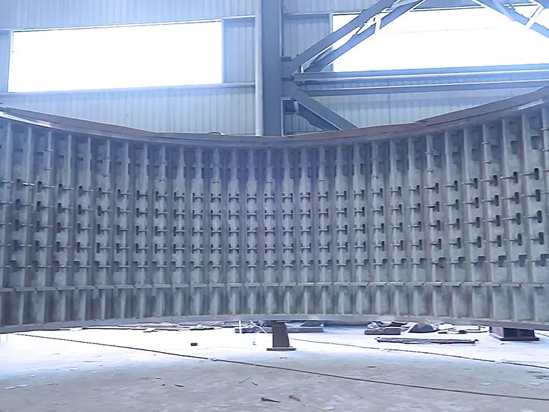
The stator frame in this case is a complex and massive welded part that demands accurate control of every production process to guarantee quality, reliability and stability. The inspection ensures its dimensional and geometric accuracy, which affects the motor’s performance and lifespan.
The outer diameter of the stator frames varies depending on the size of the unit. The large unit in this case is 4 m high with a diameter of 25 m. Its arch length is around 15 meters.
The customer needed to:
Assess the surface flatness, roughness, and weld quality of the stator frame to ensure that it meets the surface quality standards and has no significant defects or distortion.
Evaluate the stator frame’s concentricity and cylindricity to verify its compliance with the
Identify the geometric dimensions such as radius, aperture of the stator frame to validate the conformity between the actual dimensions of the stator frame and the design specifications.
Drawbacks of traditional measurement methods
In the past, the workpieces had to be placed on a CNC machine tool to obtain its flatness and radius, or measured manually with traditional measuring tools to obtain the dimensions. However, these methods had several drawbacks:
Using CNC machine too to aid in inspection of the stator frame, such as flatness and radius, may take up to two or three days.
During this period, the machine tool is occupied by the inspection process and cannot perform any other machining tasks, which waste valuable operating time. This adversely affects the overall production schedule and efficiency.
The large size of hydro-turbine components poses a challenge for manual measurement, which typically requires the collaboration of two or three personnel and results in significant errors.
Conventional measurement tools can only measure points, lines, etc., which are insufficient to fully capture features such as curved surfaces, welds, weld beading, or other occluded or deformed areas.
Traditional measurement methods also lack the ability to generate intuitive and effective inspection reports.
Scantech’s optical 3D measurement system solution
The customer was looking for efficient and intelligent ways to inspect their large welded stator frame.
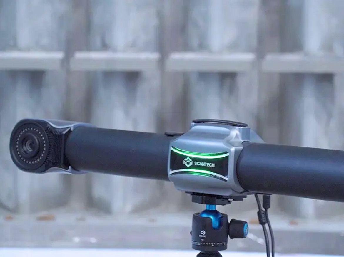
After searching for various solutions, they chose Scantech’s comprehensive 3D inspection solution featured by intelligent optical 3D measurement system TrackScan-Sharp and powerful software TrackView.
Thanks to the large-volume tracking and high-precision measurement of TrackScan-Sharp, it is capable of 3D scanning large stator frame with ease.
Workflows of 3D measurement with TrackScan-Sharp
First, the engineer used a handheld calibration rod and aligned the QR code with the tracker’s sensor to calibrate the system to ensure optimal performance. Then, the engineer placed a few markers on its surface, which helped to move i-Track during the scanning process.
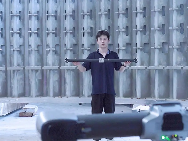
The engineer used Scantech’s 3D scanner TrackScan-Sharp to obtain the 3D data of the stator frame. The customer obatined the high-precision 3D data of the stator frame and inspected deformation in around 3 hours.
The welds, chamfers, or deep recesses of welded parts posed some structural or geometrical limitations. TrackScan-Sharp easily overcame these challenges because of its high portability and flexibility. It collected data of complex structures and hard-to-reach areas with ease.
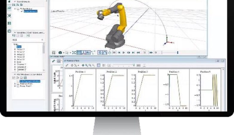
After 3D scanning, the 3D data was imported into Scantech’s in-house developed software TrackView and compared with the CAD model.
The professional software allowed them to process and analyze the data and generated a detailed inspection report, which showed the full-filed data of the part.
In this way. they measured, analyzed, and evaluated the dimensions and geometries such as radius, aperture, concentricity and cylindricity.
The 3D inspection of the stator frame was done on-site in the workshop. TrackScan Sharp was not affected by any vibration, high temperature, or other harsh conditions.
It maintained high precision and high stability throughout the measurement process and successfully completed the project.
Benefits
Large-volume measurement
TrackScan-Sharp features a large measurement volume of up to 49 m3 and a strong edge measurement algorithm, which ensures that it can measure large-scale parts without moving frequently.
This saves time for 3D scanning and data stitching. No photogrammetry system is needed to ensure high-precision volumetric accuracy.
Efficient measurement
Due to its optical tracking technology and measurement rate of up to 2.6 million measurements/s, TrackScan-Sharp can precisely measure parts efficiently. It also free up the working hour of the CNC machine tool to enhance production efficiency and lower operational expenses.
Precise measurement results
With its advanced hardware and software, TrackScan-Sharp can measure with high precision of up to 0.025 mm. The system helps to eliminate manual measurement errors caused by the large size of the part and ensures accurate measurement.
Intuitive reports
With full-field data and an intuitive colour map, engineers can analyze the deformation of a specific surface or component efficiently, which was challenging for point or linear measurements. This enabled them to enhance their process and quality control.
Scantech’s intelligent optical tracking 3D measurement solution helped the customer improve their stator frame manufacturing quality and efficiency. It also enhanced their competitiveness in the hydrotubine generator market.
Click on the following link Metrologically Speaking to read more such news about the Metrology Industry.