
Scan to CAD workflow is the process of scanning a physical object and inputting the data into CAD software. The benefit of reverse engineering an object based on 3D scan data to create CAD models is that it provides an accurate foundation on which designers and engineers can build and improve their models-instead of starting from scratch. It also makes sure that your designed product fits properly to an existing object. However, how does it work?
SHINING 3D’s ambassador Adrian Melia is a UK based mechanical design engineer with over 40 years professional experience and 30 of those focused on plastic injection molded parts for passenger car interiors. He presented a step-by-step guide of scan to CAD process during the latest webinar. Now, read on for some highlights.
Tips for Preparing a Scan to Use as a Template
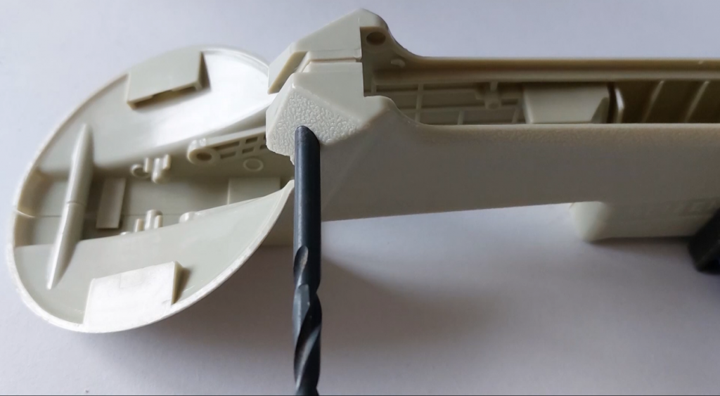
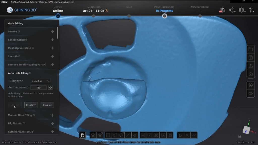
Getting the scan data is the first step. If you are using a 3D scanner to create templates for CAD models, you need to be aware of the limitations of the scanner. Small and deep holes are the main challenge because the only part of the inner wall that you will get scanned is just around the top.
3D Scanning Tip for Holes
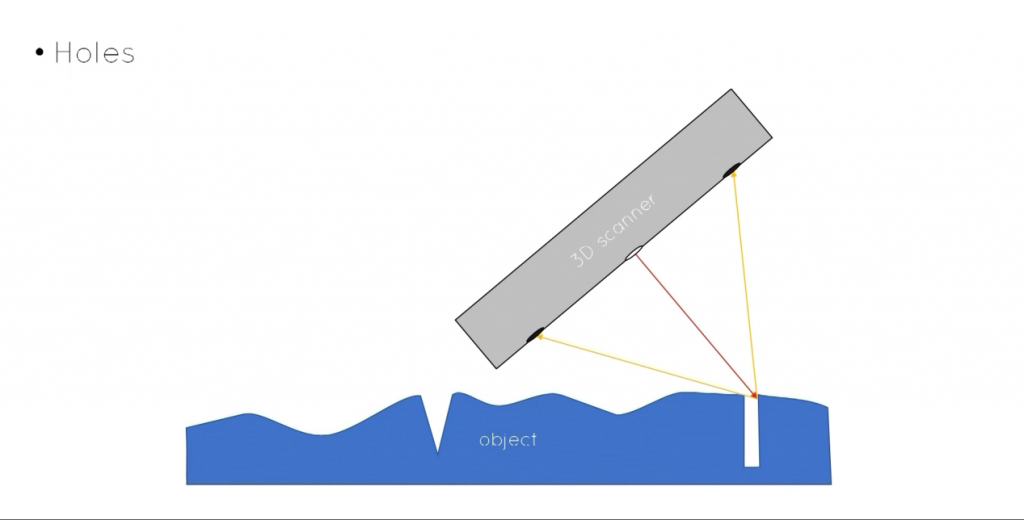
A tip is to plug the hole, leaving some of the plug exposed, and the exposed part will be easy to scan.
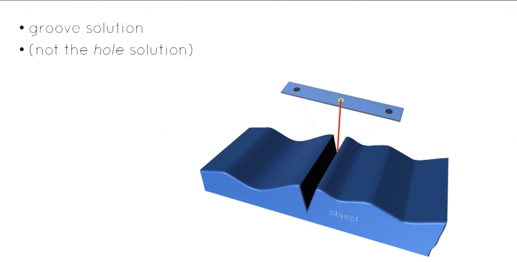
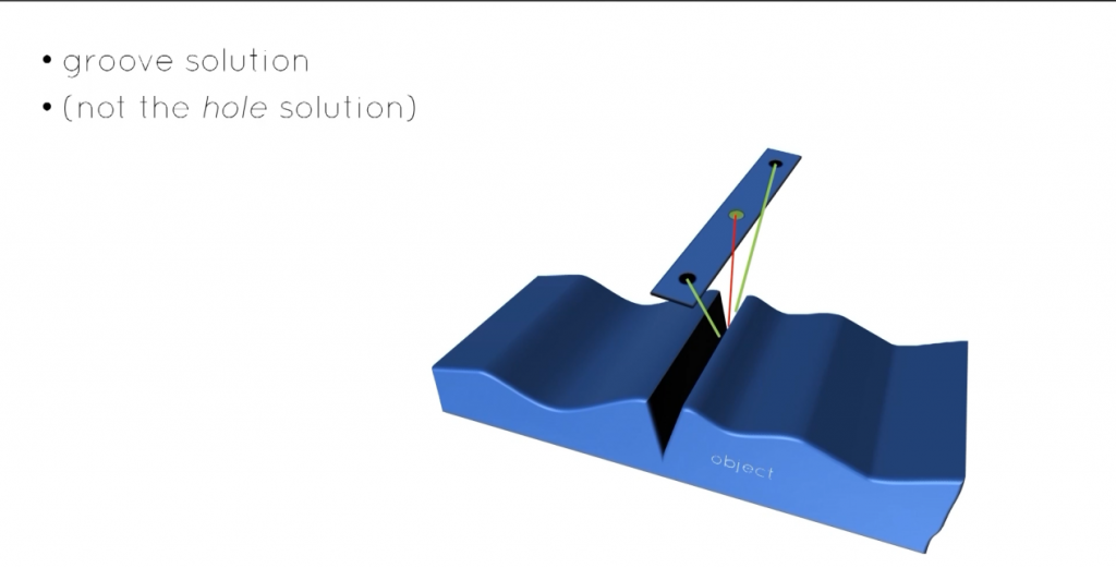
3D Scanning Tip for Deep Grooves
Deep grooves are similar. Unlike holes, grooves are not easily plugged, so keeping the 3d scanner’s line of elements parallel to the grooves will capture more data.
*SHINING 3D FreeScan Pro is the best option for scanning object with holes and deep grooves.
Another tip is to fasten flexible or distorted parts down so that they maintain the correct shape.
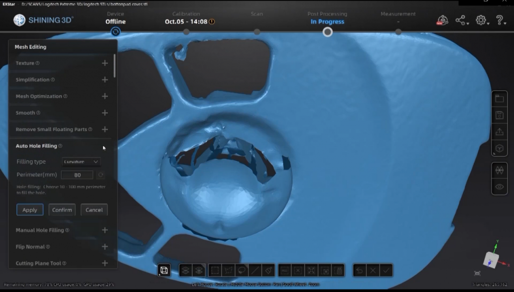
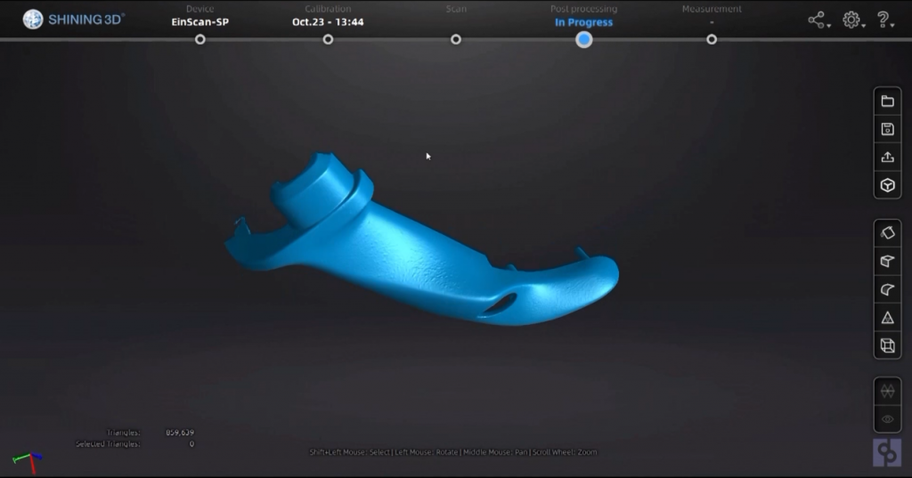
After simple cleaning of scan data, mesh is carried out. Adrian recommends saving it as non-watertight and minimizing use of optimizations, such as filling holes, smoothing, as this will make the mesh a different shape from the physical part.
Save as Non-watertight for Keeping the Organic Shape
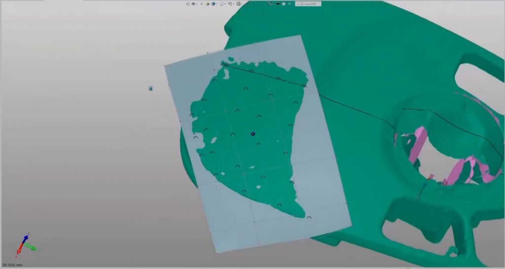
Let’s look at an example of a scan: a handle moulding done with EinScan-SP Desktop 3D Scanner. It was a black glossy injection mold that had been sprayed with dry shampoo, and EinScan-SP Desktop 3D Scanner helps us get accurate data when using tripod and turntable marker mode.
Construction Process of CAD Models
Adrian uses simple, generic techniques for building CAD models: The STL file is first imported into the CAD software-ZW3D.
A step that makes a lot of sense is aligning the 3D scan data with the CAD construction axis. This makes it easier to create accurate and detailed CAD models from the 3D scan data. when you want to align other scan that you import, you can assemble them together like CAD entities in an assembly. Then create a plane through the scan and create a cross section, which is used as the basis for building the sketch. Tracing the section using lines, arcs and splines to make a refined version of the section. Repeating this as necessary in different positions and then build CAD entity surfaces using the sketches.
Adrian shows this workflow step by step with examples in the webinar to make the explanation more specific.
Techniques for Making Simpler Surfaces through Clouds of Points
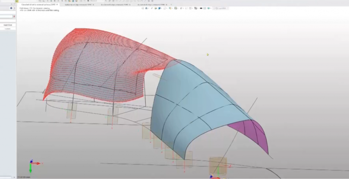
Adrian also shows the difference between surfaces generated using automatic tools and manually generated surfaces. It can be seen clearly that the number of control points on the manually generated surface is far fewer than the number on the automatically wrapped patch. In addition, there are many ripples on the edge of the automatically generated surface.
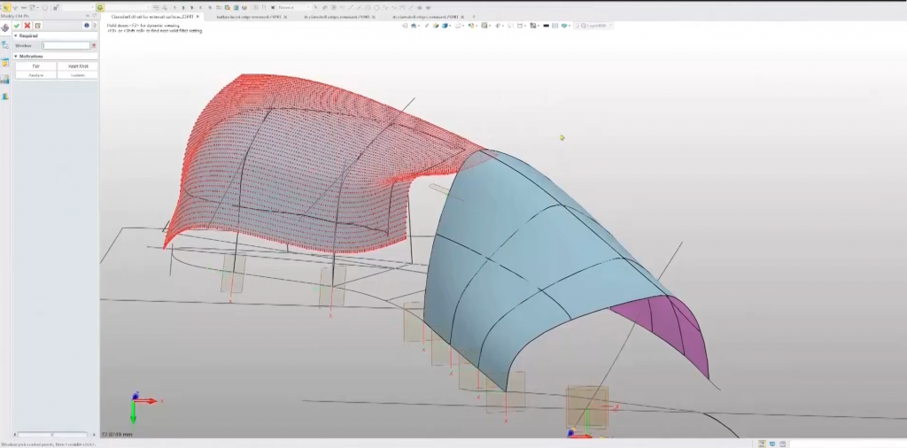
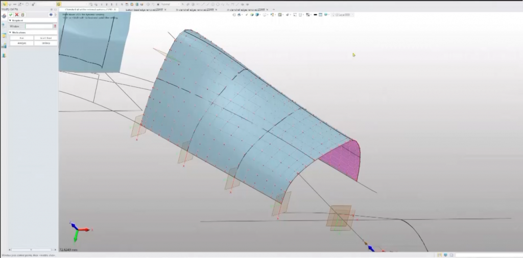
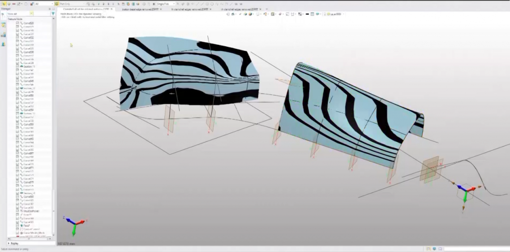
A much more controlled way of creating a surface on a point cloud was introduced in this webinar. Rather than using the point cloud itself as the target for the wrapped surface, Adrian generated a set of points just in the patch that he wants the surface to cover, and then selecting those and choosing to wrap a surface with a U&V degree of three.