Nevertheless, air gage tooling—including air plugs for inside diameter measurements—does generally come in contact with the workpiece, and may show wear after several thousand measurements or years of use. (The comments here are equally applicable to electronic plug gages.)
When, due to wear, the clearance between the gage and the workpiece exceeds the design clearance, centralization error results. The air jets then measure a chord rather than the true diameter of the part. As the distance between the chord and the bore centerline increases, we begin to see measurement inaccuracy. Another form of error occurs when the jet centerline is not on the plug centerline. In this case, the plug will always measure a chord of the part.
How much centralization error is allowable depends upon both the diameter of the workpiece and the dimensional tolerance specification. Obviously, looser tolerances can “tolerate” more measurement error. But equal amounts of misalignment will cause greater centralization error in a small bore than in a large one.
For a gage to function properly, all the jets in an air plug (or ring) must have a common recess depth and orifice diameter. But recesses and orifices may become clogged with contaminants, damaged through accident, or worn unevenly through very heavy usage. This causes another form of measurement error, called “balance error.”
It is easy to inspect for these various forms of error. Certain types of gage usage will demonstrate characteristic wear patterns. In hand-held gaging applications, wear usually occurs fairly evenly around the circumference of the plug. If, however, the plug is horizontally mounted on the front of an air gage display, then the top surface will probably experience the most wear.
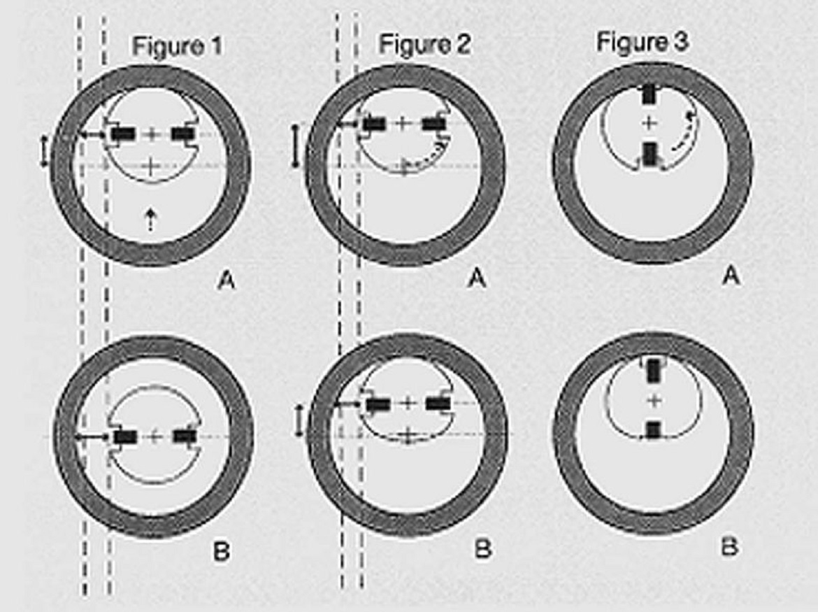
If wear is expected to be fairly regular around the circumference, start by securing the gage horizontally, with the jets also horizontal. Place a master on the plug, release it, and note the reading (Figure 1A). Then carefully raise the master until it contacts the lower surface of the plug. If the plug is worn, the readout will change as the measurement moves from a chord, through the maximum diameter (Figure 1B), to another chord. Wear may be considered excessive if the reading changes by an amount equaling 10% or more of the part tolerance.
If the gage is stationary, and the jets are normally oriented horizontally, wear might be expected on the uppermost surface of the plug between the jets. Again, place a master on the plug, release it, and note the reading (Figure 2A) . Then rotate the plug 180° and note the reading again (Figure 2B). If the surface in question is worn, the second reading will be higher.
If the jets are normally oriented vertically, then the top jet, or its recess, are of the greatest concern. The test is performed as above, by placing the master, noting the reading, rotating 180°, and reading again (Figures 3A, 3B). Alternately, the test can be performed by lifting the master ring, as in the first procedure described. Normally, two-jet air plugs automatically balance themselves when one of the jets is closer to the workpiece than the other—as is the case here, where the master is allowed to rest on the upper jet. But if one jet or orifice is damaged or worn, this test will demonstrate the gage’s inability to maintain that balance.
Plug gages tend to be highly durable, because they contact the workpiece across a broad surface area. But that doesn’t mean you can ignore the possibility of poor centralization or balance. Include these tests in your annual gage calibration program.


