
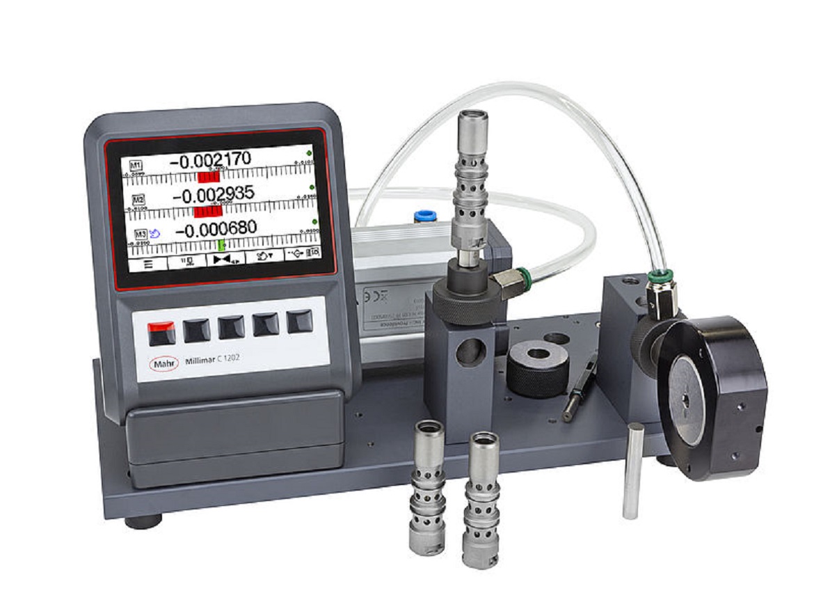
Digital indicators of today have a variety of dynamic measurement features that were previously only found in more expensive equipment. The Total Indicated Reading (TIR), Minimum (Min), and Maximum (Max) functions are among them. The indicator “remembers” the highest and lowest measured locations on a part and displays one or both of them or calculates TIR by deducting the Min from the Max.
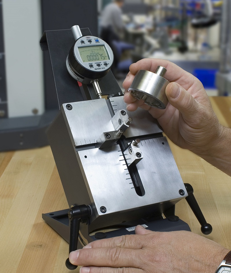
These are helpful when, for instance, measuring the height of a flat surface or gauging round pieces in a V-block fixture. Without pausing to look at the display, the operator can quickly turn a shaft through one full rotation or move a flat component beneath the gauge head. The operator has the option to choose whether to show the workpiece’s maximum or minimum ID, OD, height, depth, or runout when manipulation is complete.
Speed gauging installations can also have further complex features. The “auto-zero” function, for instance, is the electronic equivalent of the spinning bezel on mechanical dial indicators. The operator simply zeros the amplifier by bringing the gauge head into rough contact with the master, doing away with the requirement for extremely precise gauge head alignment.
Additionally, a “master deviation” function enables the fudge factor to be added to the zero setting. Imagine that your specification requires a nominal dimension of 1.99980, but that all the gauge blocks you have on hand are 2.00000. No issue. Setting your zero to 2.00000, mastering the gauge, programming a +.00020″ deviation for all measures, and presto! Without the fuss of post-measurement maths, quick and simple mastery.
The ability to switch between comparative and absolute measurements is known as a “preset value”. In other words, the indicator shows the actual part dimensions rather than gauging variation from the nominal. In the aforementioned illustration, the display would read 1.99990 if a part was.00010″ above nominal.
Today’s digital indicators let users set tolerance thresholds, and some of them have green and red lights to denote “intolerance” and “out of tolerance” states. Alternatively, for match-gaging applications, the lights might denote various part-size categories. Large accessory lights can be driven by digital output ports on digital indicators, improving the productivity of component sorting or identifying defective parts in high-volume applications.
These days, using the digital output for data collecting and SPC is fairly prevalent. To replace expensive dedicated closed-loop controllers at a tenth of the cost, gauging data from digital indicators can also be utilized to operate manufacturing equipment while it is in use.
Digital indicators of today still can’t perform some tasks quite as well as a bench amplifier. Signal combinations and remote transducers are the two that stick out the most, however, even these can be avoided. The data output signal from each digital indicator can be sent to a computer to enable signal sharing. The signals can readily be joined there in a variety of ways, including those that go beyond simple signal-sharing columns. A few digital indicators do include remote transducers, as well. This enables you to use a transducer in a gauge that would not typically accommodate a digital indicator.
Click on the following link Metrologically Speaking to read more such blogs about the Metrology Industry.