The inspection of shafts and other rotationally symmetrical workpieces is demanding due to tight tolerances and a variety of features. At the same time, measurement technology is required that can be used close to production. Here we give you an overview of the different systems, their strengths and weaknesses.
The trend towards ever smaller features and ever tighter tolerances continues. This is accompanied by an increasing demand for shaft measurement systems that are easy to program, provide efficient and highly accurate measurements and can measure a wide range of parts. They enable users to measure rotationally symmetrical workpieces directly on the shop floor, ensuring optimal quality control while production continues. Today, users can choose from three technologies to measure shafts: optical, tactile or a combination of both.
Shafts and other rotationally symmetric parts are ubiquitous in almost every mechanical system. In fact, most of the machining performed worldwide is related to producing shafts or the components that hold them together. Shafts include a variety of other elements with key functions such as splines, tapers, grooves, threads, cams and gears. These, in turn, must conform to exact dimensions in order to function reliably within mechanical systems.
Different features – same demand for accuracy
In the past, users used special hand-held measuring devices such as calipers, micrometers, snap gages or a layout surface plate to measure a typical shaft. However, many of the diameters, lengths, angles, groove widths, fillet radii or chamfers of shafts can be measured much more precisely with modern systems up to high-end coordinate measuring machines (CMMs). Growing accuracy requirements and decreasing cycle times bring additional demand for high-precision measurements directly in production. At the same time, shafts are often used in safety and performance-critical applications, so ensuring precision, quality and reliability is a top priority.
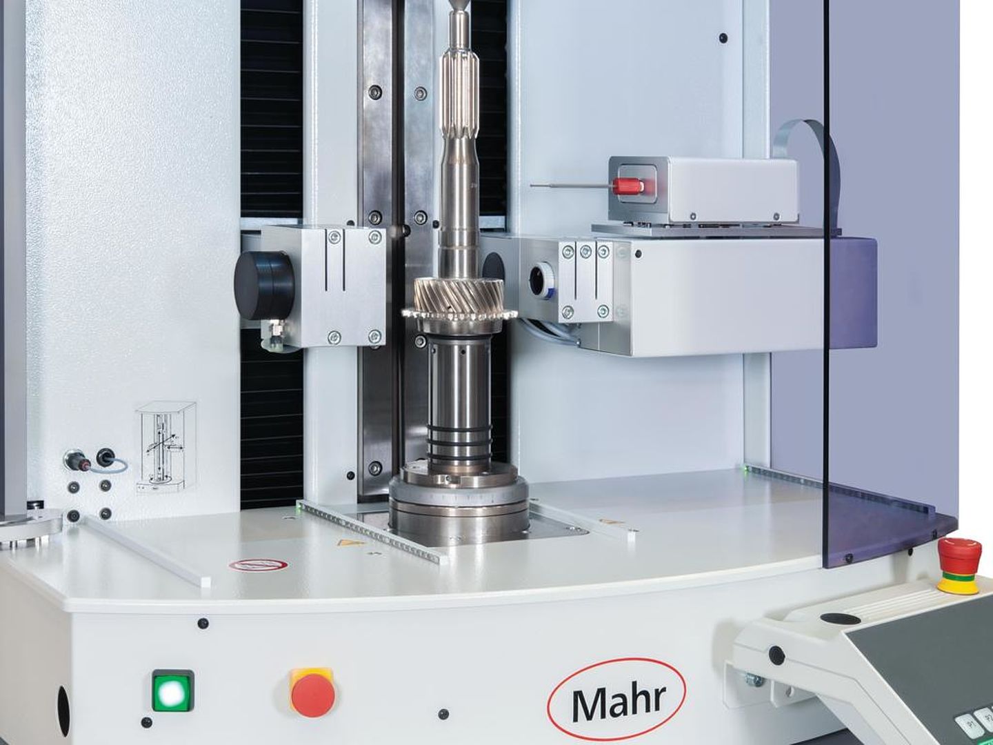
Three technologies with different advantages
Nowadays, users can choose between three technologies to measure shafts:
- optical
- tactile
- a combination of optical and tactile
Optical systems are widely used because of their flexibility and speed. However, optical systems can only measure what they can see. In this respect, an additional tactile measurement may be required. There are several options to choose from, which differ from each other in terms of measurement capability and complexity. Combination systems have therefore become increasingly popular recently: they combine the speed of an optical system with a tactile probe that can measure features that optical probes cannot detect. By cleverly combining the right optical system with the right tactile probe, users can achieve maximum precision and flexibility.
Optical shaft measurement
The market offers a wide range of sophisticated, fully automated optical shaft measurement systems that efficiently and accurately inspect rotationally symmetrical workpieces. These systems enable highly accurate measurement of numerous features in seconds, both in the laboratory and in harsh production environments – without any operator influence on the measurement results. Optical shaft measuring systems use two different methods: line scan camera or matrix camera.
The line scan camera uses so-called line scan technology to generate images of the workpiece dimensions, each containing a single line of pixels. As the object moves past in front of the camera, the image is reconstructed line by line. Line sensors are sometimes tilted slightly with respect to the workpiece axis to better measure dimensions such as edges and shoulders. Workpiece and feature diameters are represented as a series of connected dots, or pixels. The final measurement is made using a calculated image of the workpiece. However, very small features are more difficult to measure due to the lower resolution between each row.
High-resolution matrix cameras offer a modern and accurate alternative. Previously, so-called matrix array measurements were considered a somewhat slower alternative to line measurement due to the larger amount of data involved. However, technological advancements including shorter processing times and special programs for measurement optimization have closed this gap.
Today, the advantages of the matrix camera over the line scan camera are
- higher resolution and therefore more accurate and stable measurements
- measurement of significantly smaller features
- evaluation of even the smallest details thanks to zoom functions.
Tactile shaft metrology
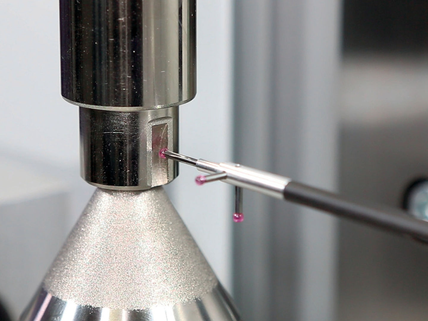
Despite its many advantages, however, optical metrology can only ever capture what is visible from the outside: the measurement process usually involves backlighting the workpiece to obtain a silhouette image for the measurement. However, this silhouette does not depict many elements, especially very detailed ones. For example, keyways or holes may be present on the shaft to serve as a reference for the location of other features. A keyway is not visible in the silhouette, but is of decisive importance for the shaft function and must therefore be measured. Therefore, depending on the feature, measurement with tactile probes is preferred. These are available in different complexity as inductive probes and 2D probes.
Inductive probes are more powerful than, for example, triggering or scanning 3D probes. Inductive probes do not simply measure individual points. Rather, the moving axes of the measurement system travel with them on the surface to be inspected, with the inductive probes continuously acquiring data points. Because inductive probes are sensitive in only one direction, the measurement systems have additional axes of motion to align the probe so that it can measure in a direction orthogonal (perpendicular to the surface) to any surface on the shaft.
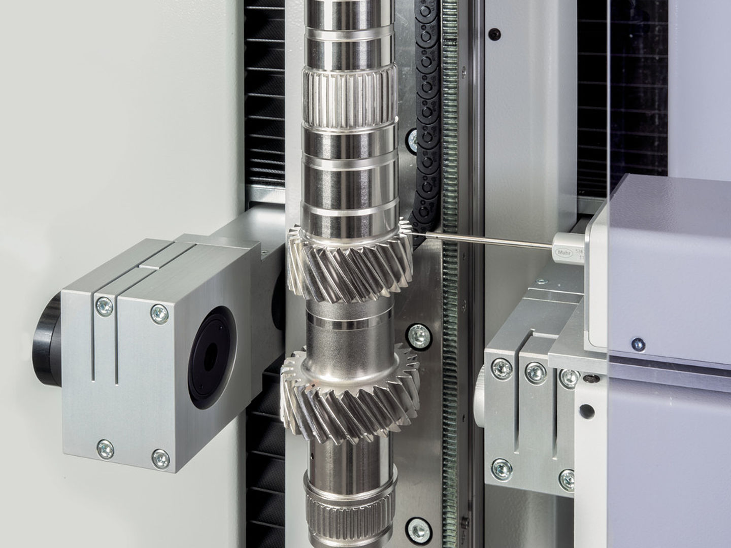
Another class of tactile probe is the 2D systems. These are also moved over the surface to continuously collect measurement points. The main difference is that these can measure in all directions of a 2D plane simultaneously, which qualifies them for measuring far more complex surfaces. For example, gears are often components of gear shafts. The use of a 2D probe system allows the complex geometry of gear profiles to be measured accurately.
Combination of optical and tactile
For even more complex features, a combination of optical and tactile measurement may be the method of choice. Correct measurement of an involute profile, for example, requires simultaneous scanning with two moving axes of the shaft system and a tactile 2D probe system capable of measuring deviations orthogonal, i.e. at right angles to the surface, at all times. This solution has decisive advantages: it enables the fast complete measurement of a shaft with many different features, e.g.
- optical: diameters, lengths, fillet radii, chamfers
- tactile: a typical spur gear toothing
in only five to ten minutes, depending on the number of teeth inspected on the gear.


