
This content was originally written and published by the AAT3D team on their website. Reproduced here from this link
By Ray Karadayi
Abstract
Dimensional measurement has been used as a part of a manufacturing system for many years and measurement and manufacturing systems are being brought ever closer to meet the current production requirements with the advent of things such as a blue light laser sensor. While the shop floor measurement equipment could be used next to a manufacturing machine and its measurement data can be digitally interfaced to change some manufacturing parameters, machine tools themselves are also being utilized to do more and more of the dimensional measurement tasks. Touch probes can be found on most of the manufacturing systems which can be utilized to automatically perform dimensional measurement tasks. Several manufacturers are now introducing analog probes that can scan parts to collect fast and dense measurement data directly on the machine. This paper discusses the integration of non-contact blue light laser sensors directly within the manufacturing system for fast data collection during the manufacturing process; using the point cloud generated from this sensor for measurement and metrology tasks and ultimately generating feedback to the manufacturing system to achieve adaptive manufacturing with point cloud metrology.
1.Introduction to On-Machine Measurement:
Dimensional measurement on the machine tools has been used ever since parts are being made by automatic machining cycles. With the advancement of the machine tools, scales, controllers, and software more advanced measurement routines are now possible to apply within the manufacturing machines. Bidirectional and fast interface capabilities already available on many of the machine tool controllers making it possible for metrology software to be utilized directly on the machine to process the measurement data and calculate advanced geometrical and tolerance characteristics of parts as they are being made. Having this capability directly on the manufacturing machine opens up the possibility of using the metrology calculations as a feedback loop to perform important corrections within the manufacturing cycle. By strategically using measurement programs through the manufacturing process enables “adaptive manufacturing” resulting in improved part quality at much less total manufacturing cycle time. The need to process faster measurement and higher density data requires the integration of non-contact sensors and powerful software that can handle such data while interfacing the machine.
2. Measurement Probes Used for Manufacturing Machines:
As the need to gather faster and more accurate data grows, new probes and non-contact sensors are being developed and integrated within the machining centers.
- Kinematic Probes: Traditionally, kinematic probes have been used for simpler applications to measure a location or a size. Although these probes produce repeatable measurements for a unidirectional measurement such as measuring along X-axis, their trigger points vary when measuring along with other directions which are required for more complex shape measurements. This requires more time-consuming calibration of the probe and presents challenges in using with a true on machine metrology application.
- Strain Gage Probes: Strain gage probes provide very repeatable measurement data which can be used by a Coordinate Measurement Machine (CMM) style measurement program producing high accuracy metrology data within the manufacturing machine. However, the measurement rates are slow as the points are taken one point at a time.
- Analog Scanning Probes: Analog probes that can collect high-density data by sweeping over the part surfaces has been used on CMMs for many years. Several manufacturers are developing analog probes for the manufacturing centers so that part measurement cycles can be reduced without having to sacrifice the measurement accuracy. The Sprint probe shown in Figure 1 is an example of an analog probe used for in-process measurements.

- Non-Contact Sensors: Non-contact blue light laser sensors which are the primary focus of this paper are integrated within the manufacturing system to help collect even higher density data at shorter times. The recent surge especially in aerospace manufacturing helped fuel the innovation in the integration of laser sensors for on-machine quick data collection. Figure 2 shows an example of a laser integration on a 5-axis machining center used for composite manufacturing.

3.Blue Light Line Scanning Laser:
A Keyence LJ-V7000 series blue light line laser is used as the measurement sensor within the machining center. These sensors are traditionally used to measure features that are moving in front of it while the sensor is stationary. Integrating such a device within the coordinate system of a 5-axis machine tool presents challenges that needs to be resolved.

- Blue Light Laser Sensor mathematical model: At each trigger, the blue light sensor produces several points along a line in a coordinate system attached to the sensor frame. This coordinate system needs to be calibrated and data transformed to merge with the machine position.

- Blue Light Laser Sensor point data: The point data gathered from the sensor model used is along a line with up to 800 points at each interface with 50 microns apart.

- Blue Light Laser Sensor focal point: The Blue Light Laser Sensor focal point is the point in the middle of the sensor active region. The machine tool is commanded to bring this point to the intended position during program execution. This is also the point where all the sensor calibration offsets are calculated.

- Physical attachment of the Blue Light Laser sensor: Blue light sensor is attached to the spindle of the machine by a specially designed bracket. This allows the sensor to be kept within the tool magazine of the machine for automatic loading and unloading.

- Blue light laser sensor tests on different materials: Tests have been performed to study the scan data quality of the generated point clouds for different materials. Several materials and parts have been selected which would be for an on-machine measurement application.
- Shiny metal surfaces:
- Calibration and tooling balls that are not coated with non-reflective material has been used to test the data quality. Since these types of artifacts are used both for calibration as well as datuming spheres, point cloud quality has been tested and results were good as in the image below.

- Shiny composite material: Both polished and rough composite materials are intended parts to use a blue light laser sensor. The quality of the data gathered in these parts was very good.

- Plastic automotive part: As plastic injection mold parts are a good candidate for a non-contact scanning application, they have been tested with also good results.

- Machined metal surface: Metal machined parts especially for aerospace engine components such as airfoils are also can benefit from non-contact scanning with a blue light laser. This type of material also resulted in very good and clean data which can be used for point cloud analysis.

- Latching of data with machine tool: The blue light laser sensor system integration with the machine must provide precise data latching between the machine position and the laser data. This is done by using a trigger signal from an external device and capturing the machine position and the laser data with time stamps. The two sets of data are merged into a single coordinate system producing the point cloud of the surface scanned. This system allows a very fast and robust data capturing between the two separate systems and very easy to integrate to the machine tool controller as it uses existing I/O channels.

4. Machine Tool as a Coordinate Measurement Machine:
Machine tools can be used to perform complex dimensional measurement functions, much like the coordinate measuring machines by using a touch probe or a laser scanner for on-machine metrology. However, there are several factors that could change the machine tool characteristics and affect the quality of the on-machine measurement data. Unlike the coordinate measuring machines, machine tools are exposed to large forces during the manufacturing process. Their geometry could also change due to thermal effects as they are located on the shop floor and generate heat by the cutting process as well. In order to perform complex dimensional measurement functions on a machining center, certain procedures must be put in place to assure the reliability of the dimensional measurements. These procedures help monitor these changes and adapt the system parameters to achieve measurement results within the specified uncertainty budgets.
- Machine Tool Geometry:
- In order to perform on machine measurement on a machining center, its geometrical integrity must be monitored, and a quick method must be put in place to verify and re-calibrate it. Although machining centers are made to be very rigid in their structures, their geometry can change due to temperature fluctuations and large cutting forces applied. On a standard 3 axis machine, there could be 21 sources of geometry errors. Although these machines have periodic calibrations, to achieve the best results for an adaptive manufacturing application, it is best to monitor and correct for these errors more frequently. Since a complete calibration of a machine tool can take a long time and would not be feasible, other quick and automated methods are adapted. Figure 13 shows examples of gages that are used for quick and automatic calibrations or verifications. Figure 13a shows a ball bar artifact that can be used to measure and verify ball bar distances and report linear and square-ness geometry errors. Figure 13b shows a simple gauge that can be applied on a 5-axis table machine to calibrate the table center and rotation axes.

- Sensor Calibrations:
For an automatic in-process measurement cycle, measurement sensors such as touch, analog, or lasers are adapted and used by the machine tool very similar to a cutting tool. If measurement feedback such as a coordinate system will be uploaded to the manufacturing system or multiple types of sensors such as a touch probe and a laser scanner used together; they all need to be calibrated not just to themselves but as a whole. For the blue light laser, a tool must be defined within the machine tool controller to identify it to the system. This definition can be done as a nominal definition defining the geometry of the tool and the actual calibrated values are held at the metrology software used for programming and analysis of the data. The following parameters are calculated from a calibration process and the measurement data are compensated during the program execution cycles are as below:
- 1) Probe Runout: This determines the probe tip deviation from its centerline. For the touch probe, this would be the offset of the center of the tip from the centerline of the machine tool. For the blue light laser, this is the offset of the focal point of the laser beam from its nominal position.
- 2) Effective radius: Since the trigger point received by the system has a delay, depending on the measurement velocity the probe radius would be smaller than its physical size. This value is used to compensate for probe radius during measurements. For blue light laser scanners, the sensor radius is assumed to have a zero radius.
- 3) Lobing Errors: For kinematic touch probes, the point of trigger depends on the contact vector with the surface. This value is like an effective radius except a different value is calculated for each approach vector. These values can be calibrated and used during the measurements by applying them based on the point’s normal vector.
- 4) Head offsets: While utilizing a 5-axis head, the actual probe position is calculated and used as the correction value during measurement cycles. This would eliminate any errors due to head misalignments. For blue light lasers, this would be the offset of the sensor’s focal point from its nominal intended location.
- 5) Sensor Attachment Coordinates: If a non-contact laser sensor is used which produces several points per measurement, its exact attachment coordinate system to the machine tool must be calculated and used as a part of the calibration. Any data received from the blue light laser would be transformed through this matrix before merging with the machine position.
- Metrology Software: In order to perform the complex mathematical calculations required for metrology based real-time decision making, a powerful CMM software needs to be integrated within the manufacturing system. Since the system is expected to function by itself without human interaction, it also needs to work autonomously within the manufacturing process. The following characteristics are required from software to truly make a machine tool function like a CMM.
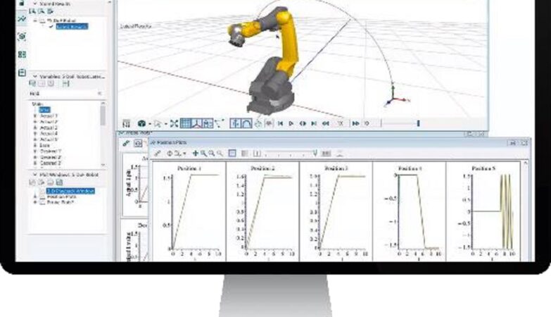
- 1) Offline Programming: A CAM style programming environment with a good machine tool virtual model, simulation capabilities, automatic path generation with collision avoidance, and complete geometrical fitting and tolerancing functionality is required for on-machine metrology. Programming languages such as DMIS (Dimensional Measurement Interface Standard) also allows to interface and collaborate with CMMs for efficient programming.
- 2) Bi-Directional Interface: A direct and bi-directional interface is a must to be able to analyze data in real-time as soon as the on-machine measurement of a feature is completed. The calculated metrology characteristics are used as a part of the on fly decision making and written back to the machine tool controller as a part of the adaptive cycle. Figure 14 shows a block diagram of such a communication between the software and the machine tool controller.
- 3) Ability to handle high-density point cloud data: While interfacing with a laser for on-machine measurement of large parts, a very large amount of data will be gathered. The software while having a live interface with the machine tool must also be able to handle the display and interaction with such data.
- 4) Geometric Feature Extractions: For on-machine geometrical feature measurements and GD&T applications, automatic feature extraction is necessary. Most point cloud systems today are offline and need operator interaction to calculate the required features. An on-machine measurement software that will interface a laser system should also have a robust automatic feature extraction capability.
- 5) Ease of Operation: The measurement programs must be integrated into the machining center like any other cutting programs for ease of on-machine measurement. This allows the programs to be integrated as a part of manufacturing cycles and can be automatically started by itself. A G-Code NC program is automatically created by post-processing the DMIS measurement program and resides in the controller. This program, like any other cutting program in the controller’s native language, is used as a part of the manufacturing cycle allowing multiple programs to work along with the cutting programs.

5. Blue Light Laser Sensor Integration with the Machine Tool:
The laser sensor is used to create a point cloud by scanning a part and ultimately calculate metrology information about the part on the machine. Part of this information will be used to provide feedback to the machine tool controller so that the benefits of having an on-machine measurement can immediately be applied to on manufacturing process. In order to achieve this goal, the laser sensor will have to be introduced into the system in relation to other tools and calibrated to other tools such as a drill bit or a water jet focal point.
- Blue Light Laser tool definition: A nominal mathematical model of the sensor is defined and entered in the machine tool controller as one of the tools. Once the calibration is performed, the actual tool data will be uploaded to the controller or can be held by the software.


- Calculate the laser sensor coordinate system: The relationship of the sensor coordinate frame to the machine tool control coordinate system has to be calibrated. This is done by scanning a calibration ball at different sections. The software then fits this data to calculate the laser frame coordinate system.

- Master ball measurement: The master ball that will be used for the calibration can be first measured by using a touch probe if one will be used together with the blue light laser sensor. Otherwise, it can be first measured by the laser sensor at the 0, 0 orientation of the head. Although having the master ball fixed within the machining center would allow the automation of the whole calibration process, a master ball can also be put in a random location before starting the calibration process.
- Calibrating multiple head orientations: The laser sensor attached by the spindle on the machine can be indexed to any orientation which the machine can move like a touch probe or the cutting tool. The head orientations that will be used in a program can be calibrated to achieve more accuracy. This is done by automatically generating programs based on the desired head positions and executing these programs automatically. A calibration program for all the head positions in a scanning program can also be created automatically to quickly calibrate these positions.
The calibration process is an automatic and iterative process. Once a program is generated, this program is stored within the machine tool controller and can be run by the operator or as a part of a program sequence. Based on the calibration quality, the software interacts with the controller and can iterate the process. Figure 18 shows the results of a calibration program.


6. Calibration Verification:
Once the sensor is installed and calibrated, a standard test like ISO 10360-5 can be performed to verify its calibration and calculate an uncertainty value for the whole system. For this test, a program is generated to measure a tooling ball by using the calibrated head orientations.

- 1) A tooling ball is measured at the 0, 0 orientation and set as the origin.
- 2) A program is created to measure the sphere for each of the calibrated angles. Typically, the following angles are used:
- a. 0, 0
- b. 0, 90
- c. 45, 0
- d. 45, 90
- e. 45, -90
- f. 45, 180
- 3) The measurement results are then compared to determine the largest deviation. This test can be completed in less than 10 minutes and generate an uncertainty statement before running the actual measurement programs. Individual feature calculations are reported to determine the uncertainty. Final sphere calculation that uses all the point clouds from each head orientation can also be performed to get an accurate statement of all the point cloud data scanned by different head positions. The following is an example of a report from this calculation:

7. On-machine part measurement with blue light laser:
- 7.1 Scanning programs: A scanning program can be created offline by using a CAD model to create a point cloud representation of surfaces. In case of scanning a trim line of a part that will be manufactured, a scanning program can be created directly from the cutting program. By scanning the surfaces along these trim lines, the exact shape of the part profile is created and can be used for further analysis.

- 7.2 Curve extractions: After blue light laser scanning a part, curves can be created from the point cloud in several ways. A 2D spline curve can be extracted automatically by specifying the section coordinates for an airfoil blade or for a mold being manufactured on a machine. Figure 21 shows a point clouds of a blade and sectional curves extracted from it. These curves can then be used to create best-fit alignments, profile reports, or calculate the airfoil parameters.
Irregular curves extracted from an NC cutting program cutting path can also be dropped onto the point cloud to create the exact trimming line profile of a part. This data then can be used to correct the multi-axis machine path to make sure the part is manufactured without requiring a long setup up process and avoid scraps. Figure 22 shows a magnified error profile of a curve extracted from a point cloud of a composite aerospace component.


- 7.3 Geometric feature extraction: Measurement of geometric features is necessary for each pre-process need such as setting up a part coordinate frame before cutting and post-process to create a full dimensional inspection report of the part. Initial part setup could be by measuring a king and a queen pin on a composite part or datum spheres located around the part to create an alignment. These coordinate systems can then be used by the reposting process to adapt the cutting program to the part orientation or simply sent to the controller as a work offset. After the part is manufactured, a finished part can be scanned and it’s trim or edge profiles can be reported as a preprocess analysis. Any drilled holes can be extracted from the point cloud and their true positions can be reported along with any other GD&T call outs creating a final inspection report. Unlike a manual or offline operation where an operator can interact with the software to perform these calculations, for the NC machine, these feature extractions are done automatically without any user interaction.
The image below shows point clouds and extracted features from a NAS (National Aerospace Standard) part. In this example, first, the three tooling balls are scanned, and spheres are extracted. An alignment is created from these spheres to match the CAD model. The calculated alignment is uploaded to the controller as a work offset and the rest of the part is scanned. Ultimately, all the geometrical features are extracted, and their dimensional reports are created.

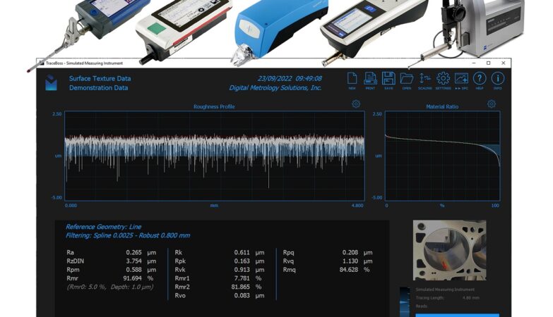
The image below shows the polar form plot of one of the circles extracted as a result of this process.

The figure below shows the positional report of one of the circles extracted.

8. Adaptive Manufacturing with point cloud data
In order to achieve a self-adapting manufacturing process, dimensional measurement programs can be utilized at several different stages of the manufacturing cycle. During pre-processing, part location and orientation can be measured and used as a work offset to help part cutting, the Part surface profile can be measured before the final finishing process to calculate tool wear and offset correction parameters for specific surfaces. As post-process final inspection, a CMM like complete measurement program can be executed to generate a final metrology analysis of the finished product for final inspection reports and statistical trend analysis.
Manufacturing large and non-rigid parts like most of the aerospace components presents challenges in many ways. Composite parts could be hard to fixture to produce a smooth cutting process. In addition to their large and usually non-rigid structures, these parts could also be deformed coming from the heat treatment process or distorted by the holding fixtures. Especially trimming a composite part with a water jet machine requires the profiles along the trimming lines to be within a certain tolerance in order to have a smooth finish and even avoid a crash.
By using a blue light laser scanner, a process can be put in place to not only setup up and prepare the part easily for the cutting process but actually, automate it so that it could be performed with minimum interaction with the operator.
1) Scan datum balls to create a coordinate system. Tooling balls used for the part alignment are scanned and their spheres are extracted from the point cloud. These are used to create an alignment according to the part setup requirements.

- 2) Scan trimming and drilling paths as defined from the cutting program: Figure 22 shows an example of the magnified profile error over a cutting tool path.
- 3) Apply re-posting to fit the cutting programs to part location and shape: The original cutting programs are processed through a reposting process and a new cutting program is generated. Once reposting is done, the regenerated cutting tool program be simulated for verification before running on the machine.
- 4)Perform the trim and drill operation: The new adapted cutting program can now be executed to produce the part.
- 5)Post-process inspection: A final scanning program is run on the finished part to generate a complete part measurement report.

9. NC Program Reposting:
NC program reposting is the process of regenerating an NC cutting program based on the measured part orientation and part shape. This process takes a nominal cutting program as an input and applies the actual part information from the measurement results such as the point clouds generated by scanning a part. Figure 27 shows the process of reposting a cutting program.

A cutting program reposting helps for two problems during a manufacturing process.
- 1) Adapting 5 Axis Parameters: A cutting tool location, usually the bottom of a cutting tool can easily be handled by applying a work offset within the controller for both part location and part rotation. However, when the tool orientation must match the actual part rotation, its G-Code program must be reposted to update the tool orientation as well. A grinding tool where the contact surface has to be at a precise orientation with the part of a water jet where the cutting vector must be precisely aligned are examples of this. Although some machine tool controllers can automatically adjust this orientation by using the work offset, in most cases this feature is not present or very difficult to use. NC program reposting for a 5 axis machine with a program using the A, B, C angles of the head or I, J, K vectors of the tool can recalculate these parameters maintaining the tool orientation with the part. Figure 29 shows a cutting path and head adapted to an actual part orientation.

- 2) Adapting machine motion to part shape: Sheet metal and composite parts that need to be trimmed may be out of its actual shape due to fixturing of its non-rigid structure or the heat treatment process. Part’s residual stresses also change its profile after a portion is removed. Especially trimming of these parts with a water jet cutting takes a long time to prepare or causes part defects. By measuring the part profile and reposting the cutting program to the actual part shape provides a very quick and inexpensive method that can also be automated. Figure 30 shows how an intended straight cut is made to fit the actual part shape through this process.

10. Reverse engineering:
In some applications, reverse engineering of the actual part shape is necessary to create a custom cutting program. A part that needs to be reworked such as a repaired blade that needs to be finished on a 5-axis machine might require a custom cutting program. In this case, the measurement data such as the point clouds or extracted curves and geometrical features can be exported to a CAM system which can then create a custom cutting program for the part’s exact location and shape.
For parts that had been repaired by welding material or parts being manufactured on additive/subtractive machines, the actual welded or generated sections can be digitized and the actual curves exported to a CAM system which can create a custom fitting cutting tool path for the parts exact shape. Figure 31 shows an example of an airfoil repaired by welding and finished by a process like this.

11. Conclusions:
A blue light laser sensor can be installed on a machining center by directly loading it like a cutting tool. This integration is very quick and very low cost and it can be adapted to multi-axis machining centers. Having a point cloud metrology capability with measurement software on an NC machine tool especially for large and non-rigid parts has great benefits.
1) Reduce setup time and cost: By integrating a closed-loop measurement system with a blue light laser on the machine, the setup up and preparation time is drastically reduced.
2) Reduce setup costs: Dedicated expensive holding fixtures are not necessary as the part setting and program fitting are done by using the measurement data.
3) Reduce dependency on external equipment: Having an on-machine measurement capability both with the touch probe a blue light laser eliminates the need to bring external measurement equipment to the machine volume such as the laser trackers or portable arms or eliminates the need to move the part to an external measuring machine.
4) Cutting program fitting: Using the point cloud data generated directly on the machine, the cutting program can be reposted and adapted to the actual part location and shapes.
5) Automated closed-loop manufacturing: As the blue light sensor can be held within the machine tool magazine, the measurement and cutting process can be automated except for manually connecting a data interface cable
6) Reduction on additional repair and scrap: Parts are manufactured adaptively by using the readily available metrology data which ends up reducing the scraps generated or the need to repair parts.
7) Increase product quality: By measuring a part on the machine without having to remove it and adjusting machining parameters based on the measurement results allows to manufacture of high precision parts. Knowing the part dimensional quality and metrological characteristics before removing it from the machine has great benefits and improves the overall performance of a manufacturing facility.
8) Manufacturing system factory control: Adaptive measuring systems work with the machining center as a peer to peer secured interface, but they are also on the network for measurement data collection and reporting. Measurement results from machines used in a manufacturing facility can be collected in a database and used to monitor the overall factory performance. Evaluating and comparing this kind of data allows better decision making and help plan for future manufacturing strategies.
In conclusion, today’s competitive manufacturing environment demands the best performance, best quality at the least costs. The state of the art machine tools and controllers enables integration of a blue light laser sensor and a metrology software within the manufacturing system and is an important part of a modern manufacturing facility.
To know more, please check AAT3D.