This is a complete guide to 3D manufacturing simulation. Find how to get started with 3D simulation, the biggest benefits of simulation, how to ramp up ones skills and much more.
Testing ideas in the real world is risky. Just ask the operators of the Chernobyl nuclear plant. If they’d had the ability to simulate how the power plant worked, perhaps the 1986 disaster would have been avoided.
This guide has two objectives:
- To introduce 3D simulation to you in case you are unfamiliar with what it can do,
- To show what 3D manufacturing simulation can help your business
This is what we will go through:
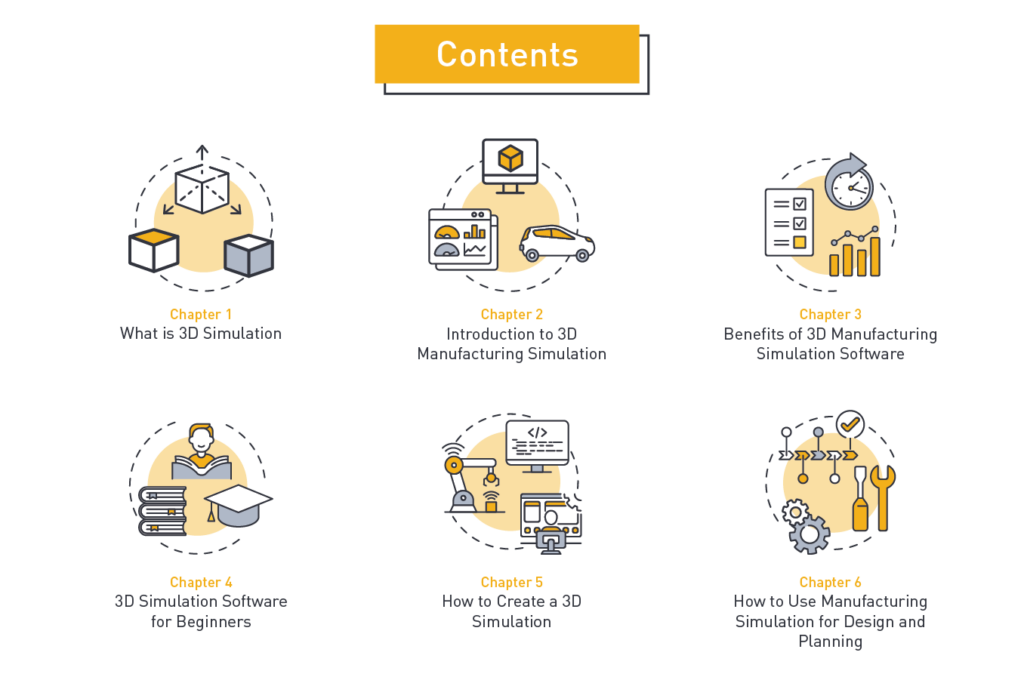
- What Is 3D Simulation?
- Introduction to 3D Manufacturing Simulation
- Benefits of 3D Manufacturing Simulation Software
- 3D Simulation Software for Beginners — Where to Learn?
- How to create a 3D Simulation
- Manufacturing Simulation for Design and Planning
Let’s go!

Let’s start with a short historical background.
A brief history of 3D simulation
People have been building physical simulators since at least the 18 Century when they were used for medical training. The 1960s saw some of the first attempts at computer-based models, although results were poor because of the amount of computation needed.
Manufacturing simulation came to the fore in the 1990s. Early products offered two-dimensional animations but as computer power grew 3D simulation became a practical tool.
Engineers soon found they could use it to model the operation of individual machines, cells and lines, and even entire factories. It was a way of investigating problems, planning new equipment installation, and exploring ways to increase output. Above all, they came to see 3D manufacturing simulation software as a tool for improving their understanding, communicating ideas, and reducing risk.
The definition of 3D simulation
This is what The Free Dictionary tells us about the meaning of 3D simulation:
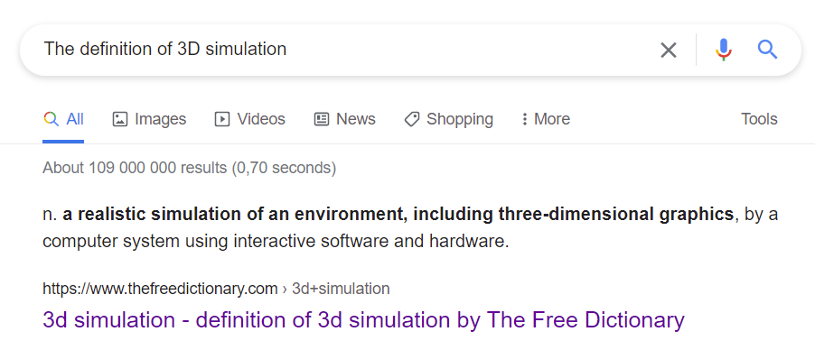
In other words, a simulation is a model or representation that mimics a real-world situation or event.
Excel vs simulation
“Why to use simulation if this can be done using a spreadsheet method?”, you may think.
Spreadsheets are a tool for simulating things that can be expressed in numbers: anticipated future financial performance, queuing times, bacterial growth rates, just to name a few. However, there are certain limitations when using Excel for simulation projects.
Advantages of 3D simulation over spreadsheets include:
- Dynamic behavior. 3D simulation provides pictures and animations that are handy for understanding the model. In modern simulation products, the pictures are rendered as images of the device or situation being modeled and can be oriented in ways that let the viewer see whatever interests them. A spreadsheet can show how the output will vary in response to changes in the inputs. It doesn’t provide any insight into complex dynamic events. It’s essentially a black box where the details of why a result occurs are hidden from view.
- Realistic variability. A 3D simulation model can display the randomness that may happen in real-world settings.
- Visual representation. Quite self-explanatory. While 3D simulation can create a highly visual and animate representation of your data. Spreadsheets are not capable of that.
3D simulation types
Before we dive deep into the world of manufacturing simulation, it’s important to consider that 3D simulation takes many forms. Here are some of the most widely used types:
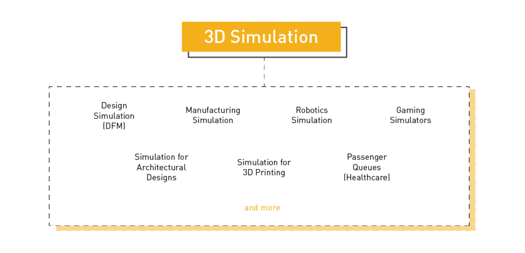
Design simulation
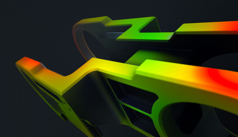
This lets a designer see how a mechanism or device will operate. 3D modeling software is used to show the impact of varying loads or temperatures on structures. In additive manufacturing simulation lets the user see how a model will print, enabling modifications to be made to the design before machine time and powder or polymer are wasted.
Robotics simulation
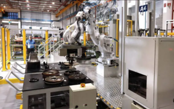
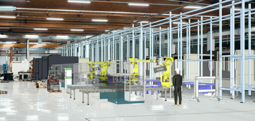
In manufacturing, it’s becoming standard practice to simulate the operation of a robot in a manufacturing cell before they are purchased and installed. This is an application where 3D graphics are especially useful. 3D robot simulation software lets the programmer view the robot end effector position from multiple positions, which reduces the risk of collisions and verifies that the robot reach is sufficient.
Gaming simulators
From flight simulators to military operations, 3D simulations have become extremely popular among the gaming community.

Simulation for architectural design
3D modeling lets architects show clients how their building will look and behave under a range of conditions. They can also model responses to environmental changes and show a building will relate to its neighborhood.

Simulation for 3D printing
Simulation shows how a shape will print, letting the designer or engineer evaluate the need for support structures and consider various build orientations. This avoids the time and expense of running a print “job” that subsequently fails.

Passenger queues
Queuing was one of the first applications for simulation and one it is widely used today. Healthcare is one very common application where it’s used to evaluate ways of optimizing staffing levels, triaging processes, and workflow organization. While this was possible with earlier 2D simulation products, the 3D simulation shows what will happen in a highly visual manner that’s readily understood by people with no understanding of how the simulation works.
Manufacturing simulation
A manufacturing simulation can be a “digital twin” of a real-world operation which allows evaluation of different production schedules and the impact of product mix and volume changes. It also supports layout planning, bottleneck optimization and continuous improvement efforts.
Manufacturing simulation products developed in the 1980s and 90s were generally 2 dimensional. These could show inventory arriving at and leaving machines, but they did a poor job of representing how work flowed through the physical factory. Consequently, they had limited value for planning factory layouts or developing and pitching improvement proposals.

Building and using a simulation of manufacturing activity is complicated. This is unavoidable: if the results are going to have any value a high level of granularity and complexity is necessary. What follows here is a high-level introduction.
To make things clear, we will break down this introduction to 3D simulation into three parts:
- How Manufacturing Simulation Works
- Model Building
- Running the Simulation
How Manufacturing Simulation Works
Simulation products come in several “flavors”; the choice of which to use depends on the application and the questions being asked. There are several techniques that can be used. Manufacturing operations are most often simulated using Discrete Event Simulation (DES). In DES a process is described as a series of events that happen in sequence. Each event is defined by what it does, when it does it, and the effect it has on the other events. DES is applicable to all types of manufacturing from single-piece production to mixed and continuous production processes.
An event is a pre-scheduled moment in time when something happens. It’s defined as an instantaneous change of state and has no duration associated with it. An event can initiate other events or change when they occur. A model is composed of a series of sequential events that define the workflow or operation sequence.
In the model, entities flow through the process and are acted on by events. In manufacturing DES, entities could be batches of work. Each batch or entity can have a different size and need different processing steps or events. Rather than modeling the time needed to process each component of a batch, the event changes the condition of the entity instantaneously. For example, it might go from “not machined” to “machined”. However, a record is maintained of how long it would take to move the batch through the operation which creates an event when machining is done.
Model Building
Manufacturing simulation starts by building a model of the operation, line, cell, or factory. This needs to reflect reality as closely as possible: any errors will reduce the accuracy and value of the results.
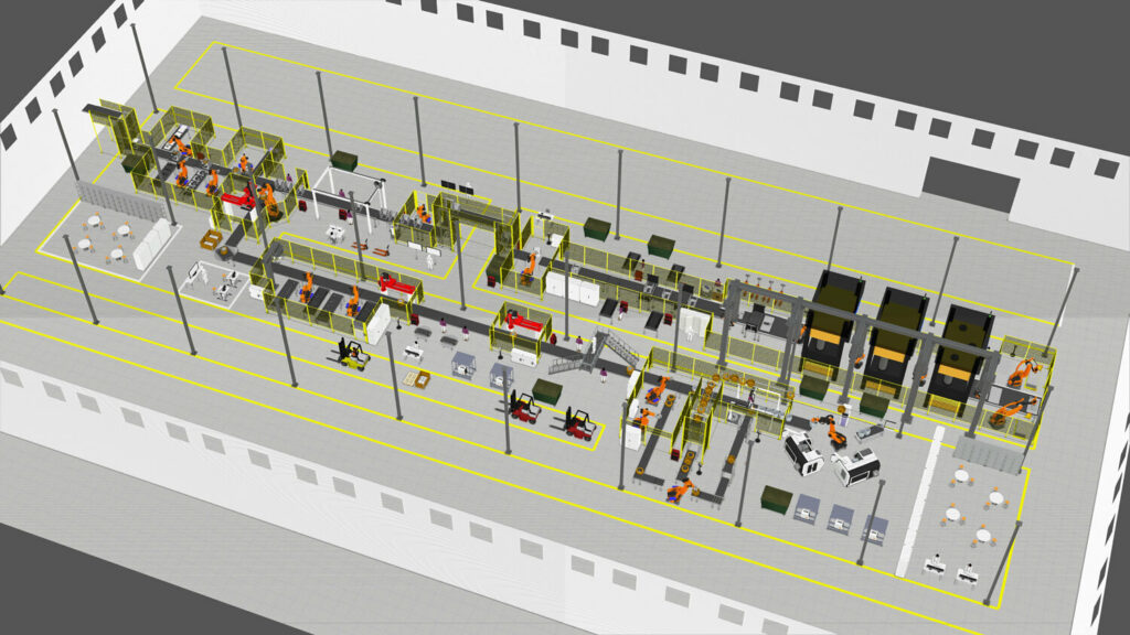
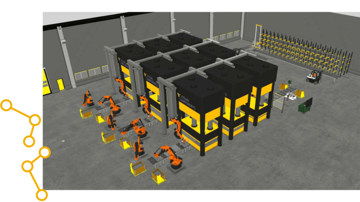
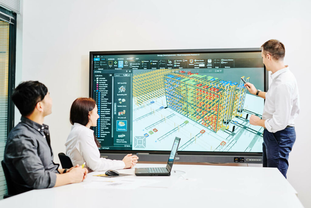
Model building entails inserting representations of the equipment that is or will be used into a layout on a computer screen. Simulation software such as Visual Components provides pre-configured machine and robot units that are brought into the model in a drag-and-drop manner.
When standard units are not available 3D CAD models can be imported. To ensure a faithful recreation of the building and existing infrastructure many users perform a 3D scan of the space and bring the resulting point cloud into the model.
Once the physical model has been created the behaviors, (processing times, conveying speeds and so on,) are added. (Many are pre-defined along with the units themselves.) Visual process modeling features within the Visual Components software allow users to manage the process flows without complex programming. Open program architectures and simple user interfaces allow easier customization in situations where there is a need to simulate special use cases.
Running the Simulation
When using 3D modeling software, an essential step after model creation is validation. This is needed to be able to verify that model accurately reflects the real-world conditions.
The same is true for manufacturing simulation: the accuracy of the model must be validated, and any errors corrected before it can be put to use. When simulating an existing operation this is straightforward: enter or load a recent production schedule or specific machine characteristics and see how closely simulation results match.
Where things get harder is validating a model of a layout or operation that doesn’t yet exist. This is something that might be done to assess material flow in an unbuilt warehouse or packaging hall. Under such conditions, it’s very important to test assumptions and gather as much data as possible to ensure accuracy. In such cases, even though the model cannot be verified against real data, different scenarios or approaches can still be compared with each other to get the ‘most likely best solution’.
Only when confidence in the model is high it makes sense to start using it to evaluate alternative scenarios, compare different layouts or carry out whatever other studies are needed. Outputs of a simulation run are presented as statistics which can be displayed in charts of various types.
Take a look at the example below.
Visual Components report statistics
Read more: 3D Production Simulation: A Complete Overview

Everyone can benefit from manufacturing simulation in a different way. It all depends on your use case.
Some manufacturers use simulation or “digital twins” for manufacturing planning. Others use it for evaluating new layouts or new equipment and for showing people how particular proposals will work in practice.
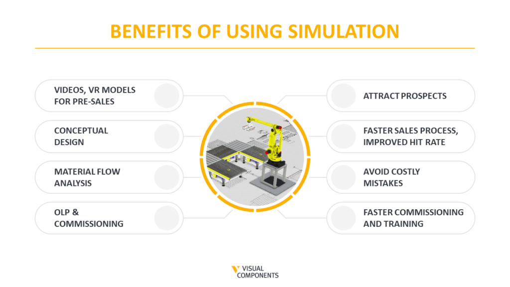
Here are the most common benefits of using 3d manufacturing simulation 👇
1. Improve response time
Working as a system integrator? Then you know that speed is a vital aspect of getting a proposal accepted. Getting visually simulated ideas in front of management helps to get the green light faster.
2. Reduce mistakes
Manufacturing operations are usually very complex, especially when there are changes in product mix and volume to consider. Using 3D manufacturing simulation software highlights issues that may otherwise be overlooked and so reduces both mistakes and missed opportunities.
One aspect stands out in particular: simulation of robot operations.
Here 3D robot simulation software, (available in products like that from Visual Components,) helps verify reach and cycle time capabilities while also guarding against collision risks.
3. Streamline communication
Decision-makers may lack a strong technical or manufacturing background. The 3D graphics and animations of simulation software make it easy to see and understand the proposal being pitched.
4. Prove to be better than your competitor
For machine builders, integrators, and consultants advising on factory layouts it’s vital to present well-developed proposals quickly and clearly. 3D simulation is an elegant and time-efficient way of doing so, which provides clear advantages over competitors.
For manufacturers themselves, many are looking for ways to leap into the industry 4.0 era but are struggling to determine what route to take. Simulation helps identify opportunities to improve that may otherwise go unnoticed and supports industrial transformation efforts.
Want more information on the benefits of manufacturing for industrial transformation? Watch this video podcast with our experts.
5. Make your case faster
Simulation is a tool for understanding problems, experimenting to find solutions, and then presenting proposals. Focused on managing costs, leaders in manufacturing organizations don’t want research studies, they need ways of resolving immediate challenges. 3D simulation helps do just that.
Here are 4 ways to use 3D simulation to sell your manufacturing planning project to management

With any powerful tool, there’s a learning curve, and 3D manufacturing simulation software is no different. To address this, we at Visual Components have developed an extensive library of education and training materials, available in our Academy.
The Academy is organized in a way that lets users acquire as much or as little information as they want. Material is presented in a combination of video and written forms. Choose any format that works best for you:
- Courses. Get an introduction to topics like using Python scripting in the Visual Components API and the basics of robot programming.
- Learning paths. Take the necessary steps in your journey from a beginner to an advanced level of using Visual Components for virtual commissioning, manufacturing design & planning or sales acceleration purposes.
- Webinars. There you will find provide topic overviews and general introductions.
- Lessons. You can dip into individual lessons as needed.
In case the sheer volume of information seems daunting, Visual Components has provided a start point for new users. “Getting Started” comprises 11 lessons intended for those just beginning to use the program. This course can be taken using Visual Components Essentials, Professional or Premium.

In any new endeavor, the hardest step is the first one. Simulation is no different.
A good start point is to watch the video below. Our very own simulation expert Reza explains how easy it is to create a cell using the Visual Components software.
Step1. Import individual elements to create the cell. This is done by inserting and rearranging objects like conveyors, machines, and robots.
Step 2. Define the operation sequence.
Step 3. Voila! Run the model.

While manufacturing simulation has many uses, most users want to investigate issues and explore improvement opportunities on the factory floor.
The “Manufacturing Design and Planning” in our Academy learning path provides the tools for doing exactly this. This learning path is a gem if you want to learn the topic of manufacturing simulation for design and planning purposes.
The path is composed of 11 modules:
- Introduction
- Layout Basics
- Importing Layout Data
- eCatalog and Component Libraries
- Modeling Custom Components
- Creating Products and Assemblies
- Creating Manufacturing Flow
- Simulating Resources
- Process Modeling Statements
- Statistics and System Analysis
- Sharing Results
After completing this path, you will have the knowledge and skills necessary to build and use detailed simulations of your manufacturing operations.
Conclusion & Next Steps
Every manufacturer in every industry is looking for improvements that lower costs, improve quality or increase capacity, and sometimes all three! Changes to factory layouts and workflow, different approaches to production scheduling and new equipment are some of the ways in which these are achieved.
The challenge is that manufacturing is always complex, so making changes involves an element of experimentation and risk. 3D manufacturing simulation software is a powerful tool for reducing that risk and finding other, perhaps unanticipated, improvement avenues.
