

DEVELOPMENT OF A NEW STANDARD FOR THE PERFORMANCE EVALUATION OF SINGLE AXIS LINEAR POSITIONING SYSTEMS
Gregory W. Vogl1, Ronnie R. Fesperman2, Stephen Ludwick3, Richard W. Klopp4,
Axel Grabowski5, Justin Lebel6, Jimmie A. Miller7, Nathan L. Brown8, Eric Belski3,
Nicholas Duncan3, and C. William Hennessey8
1National Institute of Standards and Technology (NIST), Gaithersburg, MD, USA
2Corning Inc., Newton, NC, USA
3Aerotech Inc., Pittsburgh, PA, USA
4Exponent Inc., Menlo Park, CA, USA
5Physik Instrumente (PI) GmbH & Co. KG, Karlsruhe, Germany
6Renishaw Inc., West Dundee, IL, USA
7University of North Carolina at Charlotte (UNCC), Charlotte, NC, USA
8ALIO Industries Inc., Arvada, CO, USA
INTRODUCTION
Linear positioning systems are utilized in wide-ranging manufacturing applications from machine tools to high-precision applications such as semiconductors and photovoltaics. New linear positioning systems exist with ranges of motion as long as several centimeters and positioning resolutions as low as on the order of a nanometer. The ability to meet high-precision manufacturing tolerances requires accurate knowledge of the positioning performance of these systems, yet a dedicated standard for evaluating the performance of single axis linear positioning systems does not exist. In contrast, performance standards have been used to measure the performance of single axis linear positioning systems within machine tools.
Yet the use of these standards to measure high- precision systems with off-the-shelf instrumentation and test methods can be difficult because the performance of the high-precision class of positioning systems can approach the measurement uncertainty [1]. Due to increasing demands on performance and new applications and needs, many manufacturers and users have developed their own internal methods and standards for characterizing these systems. Performance specifications based on these different methods and terminology has led to certain customer confusion. Hence, a new standard is needed with specific measurement methods for single-axis linear positioning systems to address these challenges.
Towards this end, a new standard is being created by members from industry, academia, and government in coordination with the B5 Standards Committee of the American Society of Mechanical Engineers (ASME), the Standards Developing Organization [2, 3]. The intended use of the tests described within this standard are acceptance testing of new/reconditioned systems and verification of the performance of systems already in operation.
This document focuses on the new methods under consideration for inclusion in the new standard for performance evaluation of single axis linear positioning systems.
SCOPE OF NEW STANDARD
The primary goal of the standard is for it to be used by both manufacturers and users as the main standard to guide them in characterizing the performance of their single axis linear positioning systems. As such, the new standard will describe the following for single axis linear positioning systems:
• A methodology for specifying and testing the performance of systems with travels ranging from micrometers to meters and with potentially high relative positioning performance compared to standard machine tools.
• Existing test methods and instrumentation described in machine tool standards [4-6] and new methods and instrumentation for single axis linear positioning systems.
• Unified terminology and the treatment of environmental effects and measurement uncertainty to enable performance comparisons between systems.
NEW TEST METHODS
In order for the new standard to be as useful as possible, a variety of new methods are under consideration for inclusion in the new standard. These methods attempt to “fill in the gaps” for performance evaluation of single axis linear positioning systems. Some of the additional tests being considered for inclusion are described in the following subsections.
Coordinate System Referenced Measurement A positioning system consists of a carriage, a base, guideways and bearings (five degrees of fixed constraint), actuator(s) (effecting one degree of variable positioning constraint), physical actuator interface(s), position feedback sensor(s) and intelligent electronics [7], an electromagnetic force controller, and a program with a user interface. All of these influence how the carriage moves with respect to the base not just quasi-statically as prevalently characterized but also dynamically [8] as a function of time, temperature, environment, acceleration, velocity, payload, controller parameters, etc. Additionally, every point associated with the carriage has a unique path with respect to the base as the carriage is translated, as seen in FIGURE 1.
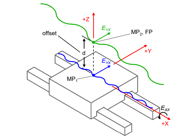
The measurements for one point do not directly characterize another point. However, by establishing well-defined coordinate systems for the carriage (moving element, csM), and the base (fixed element, csF), the motion of any point of interest can be calculated from the measurement of the linear path of a single point if the relative orientations of the carriages are also determined and the positions of the points are well defined in the csM or csF coordinate frames. The provided mathematical calculations for these enable motion calculations for an application’s functional point even if it is not the measurement point for characterization. This also facilitates error budgeting, error simulation [9], and uncertainty determination.
Incremental Step
Many industrial applications require positioning systems to repeatably make small incremental movements. As a result, vendors provide specifications for the smallest increment of motion their devices are capable of achieving. Most vendors refer to this performance capability as the minimum incremental motion (MIM), while others use terms such as minimum achievable positioning increment, minimum achievable incremental movement, least incremental step, minimum step size, and the like. Note that these terms are not used to specify the resolution in measuring the position of a system, but instead describe the smallest increment of motion a device is capable of consistently delivering.
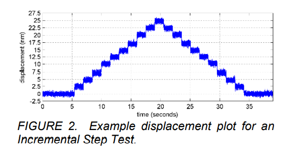
Currently, no standard test method exists for quantifying the smallest (or minimum) incremental step (or movement) that a positioning system can achieve. ASME B5.54-2005 outlines a Least Increment Test, where small steps (see FIGURE 2) are performed to illustrate a machine tool’s ability to make small incremental moves [4]. However, a quantitative treatment of what constitutes the smallest positioning increment is missing.
This new standard will describe a new Incremental Step Test and provide procedures for calculating MIM values for both unidirectional and bidirectional movements. In addition to MIM, a procedure for calculating the Incremental Step Reversal Error will be described. Accurate calculation of these performance values also requires the introduction of two additional and new test procedures: 1) In-Position Jitter and 2) Move and Settle.
In-Position Jitter
The in-position jitter refers to a measure of the amount of residual motion that occurs in a positioning system when the system is nominally at rest. When provided today, this number is often specified as simply a peak-to-peak or perhaps root mean square value. However, the procedures used to arrive at this value are at best inconsistent, and at worst undocumented. In many cases the jitter of the positioning system approaches the jitter of the available sensors. The measurement of in-position jitter is heavily influenced by a number of test conditions, each of which are elaborated upon in the draft standard. It is the objective of this section to introduce techniques for the measurement of in-position jitter so that the measures are both relevant to the product being manufactured or process being performed and are applied consistently. Doing so requires establishing guidelines for the measurement setup, the data acquisition system, and the subsequent data processing.
The measurement setup includes the sensor used in performing the measurement, the position of that sensor in the structure of the positioning system, the metrology loop, and the state of the servo system. The preferred configuration uses an independent sensor located so as to measure the motion at the functional point of the positioning system relative to the machine base via the metrology loop. As the sensor output is influenced by all motion occurring anywhere within the metrology loop, it is critical that any fixturing used in locating the sensor be well-documented and designed and located to not unduly influence the measurement. Included in the measurement setup is the documentation of the state of the closed-loop controller (likely enabled) and the state of any mechanical brakes in the system. Also included in the measurement setup is the definition of the amount of time that has passed since any commanded move has occurred to allow time for transient dynamics to settle, as well as documentation of any vibration isolation systems in place. An inferior configuration for measuring in-position jitter uses the same internal sensor that is also used as the feedback device in the servo loop. These measurements are generally much more convenient but do not clearly capture dynamic motion of the machine structure. It is also important to know and document the sensor characteristics, including but not limited to its resolution, frequency response bandwidth, measurement quantization levels, and any inherent spatial or temporal frequency characteristics.
The data acquisition system saves the real- time electrical signals from the sensor into a form that can subsequently be archived and post-processed. Salient details of the data acquisition system include the sample rate (usually time-based, but can also be triggered by position or other variable), the resolution of any analog- to-digital convertors, the presence or absence of any analog or digital filtering, the length of the data sets being collected, and the number of repeated experiments. The goal is to reduce the influence of the data acquisition system on the measurand. In general, it is best to collect samples as fast as possible and for as long as possible pending practical and economic limits to the testing. At a minimum the data acquisition should gather samples substantially faster than any known frequency component in the measurand in order to reduce the likelihood of aliasing, and for a long-enough time to adequately reflect the time scale of the process in operation.
The data processing algorithms convert the previously-captured position data into concise metrics. Of key importance is the documentation of the time over which the jitter is to be measured, and the presence or absence of any detrending or digital filtering that could be applied to, for example, attempt to separate the effects of low-frequency thermal drift from higher-frequency vibration. In the absence of other agreements, the standard recommends a record length of one second, no filtering of the data, and processing to report both a peak-to-peak value (the difference between the maximum and minimum values over a record) and a standard deviation with uncertainty bounds on both. Particular applications may benefit from processing and reviewing the data sets in the frequency domain and using the tools of Fourier transforms and
power spectral densities to isolate the motion that occurs in a particular range of frequencies. The particulars of those techniques are not planned to be included in the first release of the draft standard.
Move and Settle
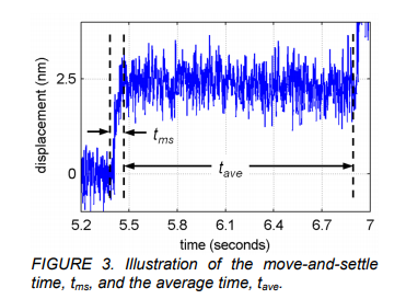
To analyze and determine the MIM values, two temporal variables to perform a commanded step must be measured and defined: the move- and-settle time, tms, and the average time, tave. As such, the new move and settle test quantifies the time required for a servo-controlled axis to move a particular distance and settle to a pre-defined position error tolerance. An illustration of these two temporal variables is shown in FIGURE 3.
Static positioning
Test procedures for measuring the static positioning repeatability and accuracy of machine tools are already described in public standards like the ASME B5.54 (2005) [4] and ISO 230-2 (2014) [10]. Since these procedures were originally developed for large machines like milling centers, and not for higher-precision positioning systems used in the most demanding applications, the new standard will modify and extend these measurement procedures.
One example is adoption of an improved measurement sequence. Prior standards typically have required that target positions used to calculate accuracy and repeatability, for example, be approached bidirectionally. In the new standard, target positions were added that can only be approached unidirectionally at the end of the travel range. This enables one to describe for the first time a calculation method for the so-called linearity of a system. This specification value is quite common in the world
of short- stroke piezoelectric-based positioning systems, but has up to now never been described in a consensus standard. These additional target positions also allow determination of the complete stroke of a system in a defined procedure.
The draft standard for the first time describes correction methods to be applied prior to evaluating data for positioning system performance. For example, many users of high precision positioning systems request the accuracy or the positioning error with respect to a dataset that has been corrected for any underlying linear component of the deviation, so that only the higher- order errors are used in the evaluation. The new standard currently adopts a similar philosophy for correcting the Abbé error with respect to a functional plane prior to evaluating, e.g., accuracy or positioning error. Prior standards typically require only that the Abbé offset distance of the measurement point be recorded in the test report. In the proposed standard, a method is described where both the positional and angular deviations are measured and the positional deviation is corrected for the Abbé error and calculated back to a defined functional plane.
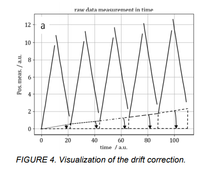
FIGURE 4. Visualization of the drift correction.
The proposed standard also includes methods for basic thermal correction. For the high-precision systems under consideration, it is often impractical if not impossible to stabilize environmental conditions sufficiently to forego correction, especially in industrial series production. This is true for short stroke high precision positioning systems with overall accuracies in the one-digit nanometer range, in which thermal variations of only a few millikelvins during the measurement may obscure and corrupt the results. To address this issue, a basic thermal correction method is described, as illustrated in FIGURE 4, that is based on an assumption that thermal drift occurs on a significantly longer timescale that any single measurement traverse of the system, and therefore that the drift appears as an underlying linear variation over the timescale of one sweep through the positioning system’s travel range.
Point Repeatability
Existing standards ASME B5.54 (2005) [4] and ISO 230-2 (2014) [10] define test methods to characterize an axis repeatability through single degree of freedom (DOF) tests focused on machine tool architecture and precision levels. Individual tests are required to quantify axial, horizontal straightness, and vertical straightness (or flatness) components of repeatability. The ASME B5.54 standard also includes procedures for using a three sensor nest to test for tool changer unidirectional repeatability. The purpose of the new Point Repeatability test methodology is to combine and expand this prior art into a test methodology that can capture bidirectional repeatability errors in three degrees of freedom with a single efficient system level test.
As seen in FIGURE 5, the standard defines a test that can be easily adjusted to match myriad end user applications, that captures all errors at nanometer level sensitivity, that captures Abbé error influence on linear repeatability, and that is compatible with many test equipment options. This methodology utilizes the multi-sensor nest concept from ASME B5.54 but updates terminology with a focus on characterization in three-dimensional space, specification of bidirectional testing, and coverage of both fixed-sensitive and moving-sensitive functional points (or testing locations).
The industry norm is to specify repeatability of a motion system as the axial repeatability, neglecting straightness and flatness repeatability errors. Furthermore, on multi-axis systems the repeatability is typically defined as only the individual axis axial repeatability error components. This industry norm correlates with the definition in prior standards where “repeatability is defined on a per-axis basis [4].” However, many applications are operating at a precision level where off-axis (straightness and flatness) repeatability errors cannot be neglected,
especially at the nanometer precision level. On an XYZ system this would require nine single DOF tests to fully characterize all three axes’ repeatability errors. This is inefficient and there is no industry consensus on how to sum repeatability errors for multi-axis motion systems.
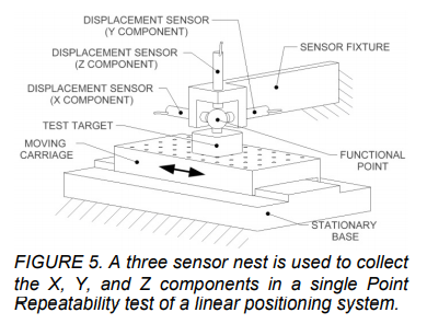
FIGURE 5. A three sensor nest is used to collect the X, Y, and Z components in a single Point Repeatability test of a linear positioning system.
This new single axis Point Repeatability test methodology is also intended to potentially lay the groundwork for a future multi-axis test that could be used to quantify all repeatability errors of all axes, as a system, in a single efficient test. The focus of the terminology and methodology defines Point Repeatability as a three-dimensional test and a “per system” test compared to prior art which is focused on a “per axis” test.
For six degree of freedom (6DOF) measurements, the linear displacement, straightness, and angular errors are traditionally measured independently and with different instrumentation. While this does allow for full characterization of a linear axis, this method also introduces potential local errors such as machine/axis bending that can cause separate measurements to become unrelated or “contaminated.” Extended time is also needed to set up different instruments, subjecting the different data sets to being influenced by environmental changes and leading to potential non-repeatability between measurements.
Future extension of this section would include measuring all six degrees of freedom simultaneously. The method of testing six degrees of freedom simultaneously involves using a 6DOF instrument coupled with the linear axis stage under test. This method is likely to prove more useful on larger stages than on micro/nano stages due to the size of the instrumentation and/or weight limitations of the linear axis.
Benefits would include having all measurements related to a single effective point or line in the work volume along the axis and reduced need to transform data sets to a common spatial location. Reduced set up and measurement time leads to a reduction in thermal and environmental effects. Repeatability between measurements of different types is improved as the state of the axis and environment is identical for all measurements recorded at each point of the test at the same moment in time.
CONCLUSIONS
A new standard for the performance evaluation of single-axis linear positioning systems is in development. The standard builds upon previous standards via the addition of new test methods for incremental step, point repeatability, in-position jitter, constant-velocity evaluation, dynamic performance, and servo characterization, among others. The primary goal of the standard is for it to be used by both manufacturers and users as the main standard to guide them in characterizing the performance of their single-axis linear positioning systems. Another goal of the standard is for it to serve as a strong foundation to be improved upon for future versions, in order to keep up with technological changes and customer needs. Currently, the new test methods are being evaluated and improved upon by various contributors. A final draft of the new standard is planned to be submitted to ASME by December 2020.
REFERENCES
- Fesperman Jr. RR, Donmez, MA, Moylan, SP. Ultra-Precision Linear Motion Metrology of a Commercially Available Linear Translation Stage. The American Society for Precision Engineering (ASPE) Twenty-sixth Annual Meeting. 2011; 52: p. 81-4.
- Fesperman R, Brown, N, Elliott, K, Ellis, J, Grabowski, A, Ludwick, S, et al. Methods for Performance Evaluation of Single Axis Positioning Systems: A New Standard. The American Society for Precision Engineering (ASPE) Twenty-eighth Annual Meeting. 2013; 56: p. 498-503.
- ASME B5 Standards Committee. B5 Machine Tools – Components, Elements, Performance, and Equipment 2020. Available from:
- https://cstools.asme.org/csconnect/CommitteeP ages.cfm?Committee=C12000000.
- American Society of Mechanical Engineers (ASME). B5.54-2005, Methods for Performance Evaluation of Computer Numerically Controlled Machining Centers. 2005.
- American Society of Mechanical Engineers (ASME). B5.57-2012, Methods for Performance Evaluation of Computer Numerically Controlled Lathes and Turning Centers. 2013.
- International Organization for Standardization (ISO). ISO 230-1:2012, Test code for machine tools — Part 1: Geometric accuracy of machines operating under no-load or quasi-static conditions. 2012.
- Miller J. Scope of Metrology Systems. The American Society for Precision Engineering (ASPE) Thirty-first Annual Meeting. 2016.
- Miller J, Hocken, R, Ramanan, V, Feng, Q. Foundation for Dynamic Metrology of Machine Tools. The American Society for Precision Engineering (ASPE) Fourteenth Annual Meeting. 1999.
- Fesperman RR, Moylan, SP, Vogl, GW, Donmez, MA. Reconfigurable data driven virtual machine tool: geometric error modeling and evaluation. CIRP Journal of Manufacturing Science and Technology. 2015;10:120-30.
- International Organization for Standardization (ISO). ISO 230-2:2014, Test code for machine tools — Part 2: Determination of accuracy and repeatability of positioning of numerically controlled axes. 2014.
For more information, check Alio.