
To reduce weight and fuel consumption, the aerospace industry increasingly relies on lightweight materials and new material combinations. That’s why the entire fuselage of the Airbus A350 XWB consists of carbon fiber composite (CFC) materials. In total, the long-haul aircraft reaches a CFC portion of 53%. In addition, Airbus uses materials such as titanium and new aluminum alloys. As a result, the A350 consumes about one quarter less fuel than conventionally constructed aircraft and environmentally harmful CO2 emissions are reduced correspondingly.
Optical Metrology Replaces Conventional Methods
However, these lightweight materials and new material combinations must meet the same high standards of performance, safety, and durability as traditional materials. Accordingly, the materials and the components manufactured from them are tested intensively. To this end, the aerospace industry increasingly relies on optical metrology. The non-contact systems provide data for part geometries as well as for 3D displacements and deformations. Static and dynamic deformations are determined based on individual points or full-field measurements. The measurement data optimize simulation and design processes and thus increase aircraft safety.
Before certification, the A350 had to pass intensive tests. Airbus supplier FACC examined fiber composite materials and components of the A350 at the Composites Lab & Test Center (CoLT), a subsidiary on the company’s premises in St. Martin (Austria). Tests for the certification of the winglets and wingtips were especially extensive. The entire element, with a length of more than 6m, was analyzed statically and dynamically in a special testing facility for long-term and peak loading. The tests also included damage tolerance testing. These analyses were necessary because the component mainly consists of fiber composite materials with metal connections.
Non-contact Measurement of 3D Displacements and Deformations
The load, fatigue, and damage tolerance tests provided information about the structural behavior of the component. Along with standard measurement techniques, for the first time, the FACC subsidiary fully integrated non-contact sensors from GOM in the test setup. Unlike conventional methods such as strain gauges, the two PONTOS systems recorded 3D displacements and deformations of the winglet.
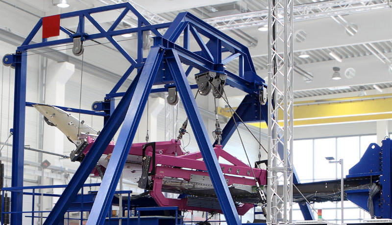
In total, the test object was 8m long, 2m high, and 3m wide – around 110 tons of steel was used on the test stand (14m long, 8m high, and 10m wide). (Fig. 1) Loads were achieved with 15 servo-hydraulic push and pull cylinders, with the force transmitted by five yokes. The two PONTOS non-contact sensors measured dynamic deformations at around 220 points, with each point being analyzed three-dimensionally in the x, y, and z-direction. In addition, more than 2,000 synchronized channels measured static strain, deformation, force, pressure, and temperature. (Fig. 2)
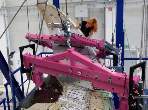
On the actual A350, the winglet and wingtip – the inside elements of the assembly – are fixed on the main wing box. In order to realistically reflect these connection points and the behavior of the main wing box during the test, a dummy wing box was used. It was specifically designed for the test and is identical to a real wing box in terms of material properties and connection of the winglet.
Complete 6DoF Analyses
During structure testing, the component was loaded statically across several stages to simulate the loads occurring during flight. In this way, the test engineers examined three scenarios: maximum torsion and maximum load upward and downward. During fatigue testing, the engineers ran through real flight profiles to analyze the behavior of the component within one life cycle. During static and fatigue testing, load factors were applied to account for variations in the material properties, and possible weight increases in the component.
For the damage tolerance tests, the winglet was damaged in advance at certain points. This way, the test engineers simulated manufacturing errors, as well as damage caused by hail impact and bird strikes in order to precisely analyze the effects on material and component behavior under load.
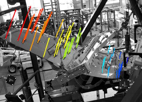
Fig. 3: The evaluation of the point-based data-enabled full 6DoF analyses. This way, test engineers could see exactly how the winglet moves in space and at which points it is particularly deformed.
Unlike conventional measurement devices such as strain gauges and transducers, optical systems such as PONTOS determined 3D displacements and deformations while additionally measuring real speed and acceleration. The evaluation of the point-based data-enabled full 6DoF analyses. This way, test engineers could see exactly how the winglet moves in space and at which points it is particularly deformed. (Fig. 3) The PONTOS system can be easily integrated into the test setup, with inspection points identified by measurement markers. Using an optically tracked touch probe, nominal positions can be determined and adapters can be measured.
Back Projection of Strain Gauge Positions with ATOS

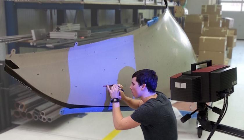
With the new PONTOS Live software module, the test run could also be measured online, enabling users to see directly in the software what happens during testing. Additionally, the measuring data could be communicated to other programs via a digital interface and could directly be processed by them. It was also possible to record and process analog signals from external measuring devices. Optical measuring systems also accelerated test setup. For instance, 200 strain gauge positions, which were defined in advance by Airbus and CoLT test engineers, were marked and applied to the component within one working day. To do so, the company Westcam, GOM‘s distributor and service provider in Austria, first measured winglet and its components with the portable photogrammetry system TRITOP, which captures 3D coordinates of objects. After the measuring data was aligned to CAD, the 3D scanner ATOS performed a back-projection of the strain gauge positions. (Fig. 4) During this process, the sensor projected the positions directly on the winglet based on the measurements. The positions are visualized as 3D elements in the CAD software. Staff from CoLT simply marked the correct points, which led to considerable time savings. Up to then, it was very work-intensive to determine the positions with measuring tapes, starting from the edges or boreholes. For demanding geometries, such as at the inner side of a leading-edge, positioning using conventional methods was very complicated, due to the strong bending. Using GOM systems it was possible in a fraction of the time. Optical metrology also allowed the positions of the applied strain gauges to be checked. They could be measured again with TRITOP photogrammetry or the handheld GOM Touch Probe and compared with the CAD data.
Simulation Verification based on 3D Measurement Data
Lightweight materials are an essential part of the aerospace industry. Correspondingly, OEMs, and suppliers test the new materials intensively to guarantee their performance, safety, and durability. Optical measuring systems can be easily integrated into different test stands; at the same time, they determine static and dynamic deformations via point-based and full-field inspections. The results are available immediately after the measurement and can be displayed in easy to understand charts, videos, and images.
One important area in which 3D measurement data is used is simulation verification. Modern flight vehicles are extremely complex, so everything is simulated during the development process. To compare the simulations with reality, comprehensive 3D measurement data is necessary instead of just a few individual signals. The results enable users to review and improve simulation parameters, as well as to optimize current and future design processes. Therefore they can reduce the number of costly test runs and consequently speed up product development. At the same time, the 3D measurement results allow conclusions to be drawn on safety risks, part durability, as well as creep and aging processes. This increases not only the safety but also the lifetime of products.
To know more, check Capture 3D.