This write-up has been reproduced from https://www.mahr.de/en-us/Services/Production-metrology/Know-how/Gaging-Tips/Basics-of-Measurement-Gaging-Tips/?ContentID=505886
Knowing how the part is designed, and where the measurement is to be made, can be key to staging the measuring instrument
Before a fixture gauge is designed, the engineer must understand what specifications must be inspected. In many respects, the gauge’s design reflects not only the design of the part but also the manufacturing processes that produced it.
Machinists must establish datums in order to machine a part accurately, and gauge designers often need to know what those datums are in order to position the part repeatably relative to the gauge head or other sensitive device. Sounds simple and straightforward, but that is not always the case.
Sometimes the parts are so large that they cannot easily be brought to the gauge, and a special arrangement might be required to bring the gauge to a section of the part. Other times, the part is so small that it seems impossible to get to the dimension that must be measured. Gauge designers are always amused when a part print—that comes in at 10 times the normal size—refers to a small land at the bottom of the bore. At 10 times the size, it looks pretty simple, although in reality it may be impossible to measure.
This is when good fixture design comes into play to ensure the measurement can be made in a way that is easy for the operator to make, and to produce repeatable and accurate results.
Take, for example, large bearings, not the 6-inch or 12-inch variety, but those that are 6 feet or 8 feet in diameter. The bearing surfaces may be curved or at an angle and call out various surface finish parameters. This may seem like an easy task, but it’s not. Most surface-finish systems base some part of their precision drive systems on gravity to lock in their axis of motion. This means they must be level to work properly. Because the goal is to measure the bearing races, which are square to gravity when the bearing is on its side, the drive will not work. This is where special fixturing comes into play. The fixturing not only must support the surface finish gauge square to the part, it also has to be able to hold a part that weighs hundreds of pounds.
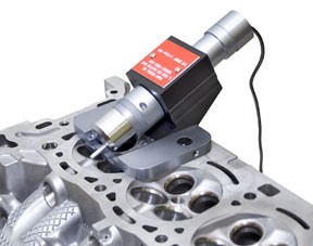
Although the big parts may be difficult, the small parts are sometimes next to impossible to measure. Take, for example, injection bores in cylinder heads. These are very small holes with critical surface-finish requirements. They are not square to any face, but rather sit at a specific angle to the top of the cylinder head. This presents many design challenges to the engineer: how to align the probe, and how to protect it from being damaged during insertion, measurement, and retraction.
In cases like this, knowing the design of the cylinder head can allow a special fixture to be designed that aligns on the cylinder head. The gauge uses it as a reference, then positions the surface finish probe at the right angle to the bore. But simply sliding the probe into the hole may not be the best solution, because surface finish probes are fragile. The better solution would be to build in a safeguard to protect the probe until it is in its final location. In this example, a special mechanical switch keeps the probe retracted until insertion is complete and the probe is in position.
In addition, we also need a way to check the calibration of the system. Because the probe is set within a fixture at the proper angle, and since it would be too time-consuming to take it apart every time it needs to be checked for calibration, the solution is to also stage the gauge for proper alignment to a precision surface-finish patch. In this case, the calibration fixture simulates the part, but with a precision patch placed in the location of the bore.
Knowing how the part is designed, where the measurement is to be made, and how these two interrelate, can be the key to staging the measuring instrument.
ABOUT THE AUTHOR
George Schuetz
George Schuetz is director of Precision Gages at Mahr Inc.


