

Do you have a lot of experience with 3D scanning for the foundry and casting sectors? Don’t forget to watch Bruce’s most recent webinar!
In the foundry and casting industries, Bruce has used measurement equipment as a manager of accounts at SHINING 3D. He discusses the variations between conventional manufacturing techniques and 3D scanning in this webinar. Bruce also provides examples of the applications for metrology 3D scanners and the kinds of outcomes you might anticipate.
With his advice, you’ll be prepared to pick the ideal 3D metrology scanner for your requirements.
Traditional measurement tools and their limitations
Casting and foundries are crucial to manufacturing because they provide crucial components for practically every sector. The majority of products, whether from the automotive, aerospace, building, or consumer goods industries, have gone through foundry and casting.
These procedures use a lot of hand tools. Bruce points out that the standard tools for measuring in the business are a steel ruler, a vernier caliper, a caliper, and a filler gauge.
These conventional measuring instruments have the benefits of being simple to use, affordable, giving instant measurement data, and not requiring batteries.
However, employing such tools takes time and, if misread or improperly used, can easily produce erroneous findings. These instruments gradually become unable to meet the increasingly stringent requirements as the sector develops and demands higher precision.
The use of 3D measurement instruments like coordinate measuring machines (CMMs) and 3D laser scanning arms is common in manufacturing because of this. These instruments improve accuracy and reduce some of the dangers associated with hand measurements.
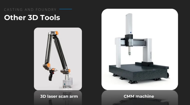
But CMMs and laser 3D scanner arms also have limitations of their own. They can only gauge what is within their reach and both represent a hefty initial expenditure. This means that a CMM can only measure objects that fit inside its frame. That is the measurement arm’s length for a laser.
Several additional restrictions are brought forth by industrial coordinate measurement equipment. Because they require a certain working conditions (such as low humidity and temperature, no vibrations), they suggest high operational costs. Additionally, they are very slow and take a long time to measure massive items at full scale. Not to mention, they have trouble measuring items with curved portions or limited zones (such as pockets or holes).
Metrology 3D scanners vs. CMMs and 3D laser arms
Taking the above into account, Bruced shares six benefits of using 3D scanning in the foundry and casting industry.
● Faster speed: As the laser moves across the surface of an object, thousands to tens of thousands of data points can be recorded per second.
● High accuracy: Metrology 3D scanners like ones from the SHINING 3D FreeScan series can offer an accuracy of up to 0.02mm.
● Good environmental adaptability: Temperature, humidity, light, and vibrations have little effect on scanning, and 3D scanners can be used widely in the workshop.
● Portable: Handheld 3D scanners are lightweight and compact. They generally come with a travel case, making them easy to transport even on a plane trip.
● Cost-effective: Non-contact 3D scanning and inspection tend to be faster and smoother to carry out, all while providing certified quality and precision.
● User-friendly: 3D scanners and their software are intuitive to use and set up. Plus, handheld metrology 3D scanners enable easier access to narrow, confined areas.
Main applications of 3D scanning casts and molds
Casting and mold factories leverage 3D scanning for numerous use cases. Most of them can be grouped into three common use case types:
● Reverse engineering, 3D-scan-to-CAD, and 3D modeling
● 3D inspection and quality control
● CAE (computer-aided engineering) and virtual assembly
The most widely used applications are reverse engineering and 3D inspection. 3D scanners are used in factories to inspect or reverse engineer a variety of items made of various materials. These include foam or wooden templates, metal molds, unfinished casting components, precise milling components, and more.
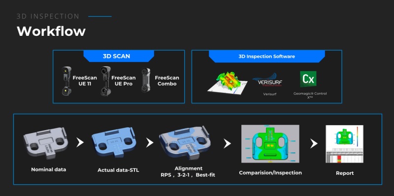
The typical 3D inspection workflow for casting and foundry parts goes something like this:
1.3D scan the part to obtain and export 3D data, usually in the STL file format.
2. Import the scanned data to 3D inspection software – like Geomagic Control X or Verisurf – and align. There are several methods to do alignment, the most popular ones being best-fit alignment, RPS alignment, and 3-2-1 alignment.
3. Create the deviation map, GD&T, or other inspection items and export the inspection report.
Real examples of 3D scanning in the foundry and casting industry
Bruce provided a few examples from real-world situations after discussing the advantages of 3D scanning and outlining its primary applications. These ought to give you a greater idea of how metrology-grade 3D scanning can be put to use in casting and foundries.
Lost foam pattern: 3D first article inspection
In lost foam casting, a mold is formed by coating a pattern composed of expanded polystyrene (EPS). The molten metal is then poured into the mold, vaporizing or burning away the design to leave a perfect metal casting in its place.
However, it is crucial to calculate the deviation of the foam pattern and contrast it with the CAD model before casting. The “3D first article inspection” stage is referred to as such. In this use case, the customer immediately 3D-scanned the pattern on-site using a FreeScan UE 3D scanner. The results showed an extraordinary amount of detail and were very accurate.
Wooden Pattern: Axis Body Offset
For subsequent sand casting, wooden patterns are frequently utilized as prototypes. Their size and shape, like those of the majority of prototypes and molds, directly influence the caliber of the finished item.
The main shaft of a wind turbine can be seen in the wooden mold in the webinar screenshot up top. It measures 5 meters high by 4 meters wide. The wooden pattern axis body can readily shift during production because of its extra-large size.
The group decided to perform a thorough examination with the FreeScan UE Pro to ascertain whether and how much of an offset there is. When digitizing huge objects, our metrology 3D scanner’s integrated photogrammetry ensures accurate and consistent data.
The team was able to 3D scan the entire 4-by-5-meter mold in about 35 minutes, excluding climbing and wiring.
CNC programming verification
The mold in the image below was manufactured with a CNC milling machine:
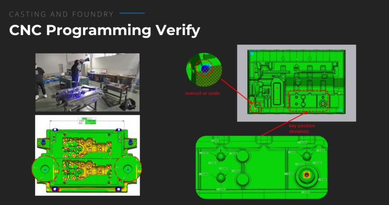
Prior to mass-producing the item, it is best to verify the milled part to ensure that it was manufactured appropriately. Here, the team was able to quickly identify errors (such as reference hole position variation) and adjust the CNC programming by comparing the 3D scan to the original CAD design.
Other common use cases
Virtual assembly and wall thickness inspection
Virtual assembly is the process of putting together several components of a single product in 3D and online. Simulating the final assembly is done to ensure that each component works well with the others. Virtual assembly can help engineers and designers improve their products even if the parts fit together properly.
With a 3D scanner and the appropriate 3D inspection software, which includes built-in virtual assembly capabilities, this method is simple to use. Wall thickness is one of the key characteristics that might be considered for the ideal fit.
The thickness of the casting walls—mold and mold, mold and core, and core and core—is referred to as wall thickness. It is a crucial component of the dimension inspection process that can be examined before beginning the actual casting process.
Maintenance and Re-design
SHINING Accurate 3D digital data of various parts and components can be produced by 3D scanners. These “digital twins” are important for reverse engineering and design optimization, and they can also be stored for upcoming maintenance. In the design of jigs and fixtures, for instance, this workflow and application are fairly common.
Conclusion
Bruce covered the advantages and uses of 3D scanning in the foundry and casting industries in this webinar. He emphasized the drawbacks of alternate solutions including CMMs and 3D laser scanning arms as well as the shortcomings of conventional measurement equipment. To get around these restrictions, metrology 3D scanners like the FreeScan UE series—which offer quicker speed, high accuracy, portability, and affordability—are introduced.
Reverse engineering, 3D inspection, and virtual assembly are the principal uses of 3D scanning in foundries and casting. Its application in tasks including pattern inspection, first article inspection, and CNC programming verification is illustrated by real-world instances.
The webinar concludes by highlighting the benefits of 3D scanning for industry precision and productivity. As an accurate and dependable option for foundry and casting applications, the FreeScan UE series is suggested.
Click on the following link Metrologically Speaking to read more such blogs about the Metrology Industry.