
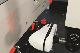
Laser scanning provides highly effective inspection.
Whatever the product, be it a car, hand drill or mobile phone, customers expect its tightly-toleranced parts to fit together and function perfectly and at the same time be of high quality and attractive design. But how do manufacturers ensure this level of precision without delaying the development and launch of the product?
The answer is to digitise the 3D shape and features of the prototypes with a non-contact laser scanner mounted on a coordinate measuring machine (CMM) or articulated arm and compare the results to the original CAD designs. It is much faster to inspect a part this way than to use a touch probe to take discrete measurements. With tens of thousands of points per second being captured by the laser and added to the point cloud, a complete inspection cycle is often between five and 10 times faster than tactile probing.
Furthermore, with the latter technique it is impossible to know what is happening between two adjacent discrete points, so the data is very sensitive to imperfections in the geometry being inspected. Parts that have flatness and roundness errors, edge rollover or burrs are particularly problematic. Radius compensation error is a further difficulty with tactile probing. When a stylus makes contact with the edges of a hole, for example, radius compensation may result in unexpected measurement points if a neighbouring surface is touched first.
Keeping down costs
OEMs are keen to keep down costs at every stage of the production cycle. The problem is that even a limited number of touch probe measurement points involve considerable programming overhead and creating tactile scanning cycles is even more complicated, time consuming and expensive. On the aerofoil surface of a turbine blade, for instance, 5-axis analogue scanning requires elaborate CMM programming to ensure that the probe tip continuously follows the part surface without colliding with it or the machine structure. Furthermore, the component needs to be clamped in a costly fixture.

With non-contact laser scanning there are fewer restrictions, so costs are reduced. It is not even necessary to datum the component; it can be placed anywhere on the table in any orientation or held in a simple fixture. Programming laser scanning cycles is easier and faster, both online and off-line, requiring only simple parallel sweeps of the head with short motion paths and limited or no head indexing.
Interactive, multi-sensor Nikon CAMIO software streamlines the creation of scan macros. The scanner moves along linear and polygonal paths generated automatically or manually from the CAD model to keep the surface of the component within the field-of-view of the laser scanner. For surface areas falling outside the path, virtual point cloud simulation reveals where to generate additional scans. Lower operational costs and further increases in inspection productivity are the end result.
Laser scanners are often used in combination with tactile probes for alignment of a part or for a mixed measuring routine that might include accessing difficult internal features. Nikon Metrology’s multi-sensor CAMIO software provides a rich programming environment, with intuitive software tools for both tactile and laser scanning applications. A variety of inspection tools is available including full part-to-CAD comparison and intelligent feature extraction with GD&T tolerancing and profile analysis.
Better insight enables quicker decision-making
Early detection of product quality issues and understanding the root cause of a problem are essential to rapid development of a new product. Digitising parts up-front and inspecting the virtual digital copies provides a high level of detailed knowledge by streamlining metrology operations and embedding them into an integrated, CAD-centred, design-to-manufacturing process.

The low-noise point cloud captured by a laser scanner allows a manufacturer to generate and access the required information. Nikon Metrology’s DMIS-based CAMIO software automatically filters the data and produces smooth, highly detailed meshes that are aligned with nominal CAD geometry using best-fit, feature-align or other techniques. A complete digital model comprising complex freeform surfaces and dimensional information is derived in minutes rather than hours, or hours rather than days.
Comprehensive reporting simplifies understanding the problems and facilitates collaboration between different departments, with tabular information and colour-coded deviation reports that are easy to interpret showing clearly the areas of concern and what is likely to have caused them. Underlying metrology data can be consulted by clicking on any location of interest.
Laser scanning allows detailed feature information to be obtained from the measured point clouds. With hundreds of points measured on holes, slots and studs, the features can be extracted more accurately compared to tactile probing, during which often only a few points are measured. Full GD&T analysis toolboxes are available to inspect location, cylindricity, parallelism and much more.
3D scanning reduces product development time, since once the digital model of a prototype is available, product verification, engineering analyses and other functions can take place concurrently. On-screen, virtual assembly of multi-part products speeds fit and function analyses and shortens the prototyping phase. Often, as complete parts are measured and more information is available, several iterations can be eliminated altogether from a product development cycle.
In the automotive industry, for example, Nikon Metrology XC65Dx-LS Cross Scanners with continuous wrist interfaces on horizontal-arm CMMs frequently underpin diagnostic measurement of sheet metal components and body-in-white (BIW) assemblies. Inspection is much faster and economical compared to touch probing, raising efficiency and reducing the time needed to diagnose problems. A vehicle’s entire sheet metal structure can be inspected to very close tolerances and virtually assembled, showing the interaction between the panels and allowing parts issues to be separated from process issues. Complete vehicles are also inspected, mainly for gap-and-flush spacing between car panels.
Challenging surfaces scanned easily

Components produced from flexible, sensitive or fragile materials need a metrology solution that does not cause the part to move or mark its surface during inspection. Manufacturers of such products will almost certainly look beyond tactile probing to 3D laser scanning.
Shiny and multi-coloured surfaces do not cause a problem either. To capture data from surfaces of varying color or high reflectivity, Nikon Metrology’s laser scanners dynamically adapt the laser source intensity point by point. The capability allows different sample materials and surface finishes to be inspected without operator intervention and also copes well with reflective surfaces and abrupt transitions under any lighting condition, without the need for matt powder spraying or other surface preparation. Only transparent parts and those with a mirror finish require manual preparation or perhaps tactile scanning.
Intelligent intensity adaptation also helps automatic laser scanning of similar parts at different stages of manufacture, initially dealing perhaps with bare sheet metal parts and finally scanning finished products painted in any color.