
This content was originally written and published by the Sensofar team on their website. Reproduced here from this link.
Everything is possible with the S neox Five Axis. Steep angles and very small cutting-edge measurements of a few micrometers are no longer a problem for 3D optical profiling
Thomas Forrer– Head of Research & Development (right), Paco Neuhaus– Application Engineer (left)
Whirling inserts are used to produce threads. The whirling process is complex, that’s why there are many different angles (lead angle, angle of rake, clearance angle) on an insert (Figure 1a). In addition, there are inserts with up to 3 teeth on it. This makes it very difficult to measure an insert.
For previous quality assessments, one had to rely on simple optical devices for assessing the dimensional accuracy and on stylus devices for measuring roughness. The informative value of these measurements, however, is very limited. In addition, the parts often had to be destroyed so that the desired size could be measured. In order to constantly improve the quality of our tools, there is a need for a flexible device to measure and assess both critical dimensions and surface roughness of cutting tools.
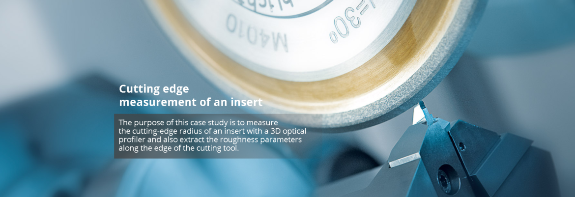
The purpose of this case study is to measure the cutting-edge radius of an insert with a 3D optical profiler and also extract the roughness parameters along the edge of the cutting tool. A schematic drawing of the insert to be measured is shown in Figure 1b.

The cutting-edge radius is very important for a good tool for life expectancy. For this particular application note, we used the S neox Five Axis 3D Optical Profilometer in Focus Variation HDR mode (Sensofar), in conjunction with a 100X Objective magnification, to acquire the cutting edge 3D topography of an insert (Figure 2).

The insert was held as shown in Figure 3 with an elevation angle of 63.5º.

Once the topography was acquired, the data was sent out to the SensoPRO software ‘Edge’ plug-in for automated data analyses. This software module can automatically detect the cutting edge orientation and computes a certain number of profiles that are transversal to the edge. For this particular example, we chose up to 30 profiles, from which the cutting edge radius, among many other parameters listed in Figure 4, were computed.

The SensoPRO software allows for visualization of each parameter and provides some statistics on each parameter (i.e., mean value, standard deviation, minimum and maximum). As shown in Figure 5, the average radius of 30 profiles is 5.14 µm with a standard deviation of ±0.35 µm. It is also worth mentioning that the software allows setting a tolerance range and exporting the results in a Pass or Fail Report, in our case, we set a minimum and a maximum cutting edge radius of 4.7 and 5.7 µm, respectively, which can be seen at the bottom plot in Figure 5 (i.e., orange region).
Finally, one last parameter of interest is the roughness at the edge of the cutting tool. This information is provided automatically by the software in the form of many common and standard parameters such as Ra, Rz and Rq, among others. In this particular case, the cutting edge had an Ra of 0.05 µm.

The 3D optical profilometer S neox Five Axis makes it possible to quickly and flexibly obtain the key parameters necessary for the continuous improvement of our tools, such as the cutting edge radius, clearance and rake angles, or even the roughness at the edge.
In this particular case study, we successfully measured an average cutting edge radius of 5.14 µm and a roughness Ra value of 0.05 µm at the edge of the cutting tool. This information was easily obtained using the Ai Focus Variation technology, with a 100X objective magnification, and with the application-specific software, SensoPRO (‘Edge’ plug-in).
Having three measuring methods present within the same sensor head (i.e., Confocal, Ai Focus Variation, and Interferometry) allows for a very flexible measurement of different measuring tasks on various parts. From very smooth and shiny to heavily textured, rough surfaces: everything is possible with the S neox Five Axis. Steep angles and very small cutting-edge measurements of a few micrometers are no longer a problem for 3D optical profiling.
To know more, please check Sensofar.