Geoform turns to PolyWorks|Inspector’s best-fit capabilities and salvages parts that would otherwise have been scrapped.
Geoform, Inc. (Inglewood, CA), also known as Precision Measurement Laboratories, has offered metrology services since 1986. As it grew, the company expanded into CAD/CAM, tooling and fixture manufacturing, and short-run production. Yet, its core business remains dimensional inspection, with emphasis on complex aerospace, automotive, and medical parts.
The Challenge
Over the years, Geoform has seen the tools, techniques, and approaches to quality control evolve. With recent advances, it has become more important than ever to stop and consider which tools are the best for the job. Steve Farentinos, Geoform’s President, cites his company’s work with Weber Metals Inc. as an example of these changes, as well as the importance of selecting the best tools.
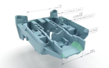
Weber Metals, a full-line aluminum and titanium forging supplier, is one of a growing number of companies that use model-based definition (MBD) to document its products without dimensioned drawings. According to Farentinos, “Quite a few parts come through our doors with only CAD data and instructions to inspect the profile tolerances and a few key dimensions. Inspecting to print is no longer the norm.” This approach offers big savings, especially for complex parts with many features. “It cuts back on the time it takes to make dimensioned engineering drawings, plus it removes a lot of work from the inspection process,” he said.
The Solution
For a profile inspection of Weber Metal parts, Geoform turned to a Faro laser scanning system and the PolyWorks® software solution. From start to finish—scanning to reporting—some inspection jobs are completed in less than one day. “It is a huge difference! We can complete inspections of relatively complicated parts in a few hours. Using the old-fashioned way, these same parts could take three or four days,” he said.
When a project comes in, Geoform uses the tool that’s the best for the job!
Farentinos was quick to note that “old-fashioned” is not the best term because Geoform continues to rely on these “established” methods. Although the Faro portable CMMs (PCMM) are widely used, he stated, “When a project comes in, we use the tool that’s the best for the job.” These tools include two Faro arms, three stationary CMMs and InnovMetric’s PolyWorks|Inspector™ software solution.
According to Farentinos, CMMs are the workhorses for jobs that are high volume, require higher accuracy, and will run for a long time. The Faro arms excel at the one-off projects or first-look parts for design evaluation and process qualifications. They are also ideal for capturing the contours of complex castings, forgings, and formed metal or plastic parts when inspecting profile tolerances. For these jobs, Geoform uses both a laser scanner and a touch probe in the same measurement session. “We do hard probing on some prismatic features and scanning for everything else. The hard probe is helpful if you need to quickly measure some setup features for a preliminary coordinate system,” he said.
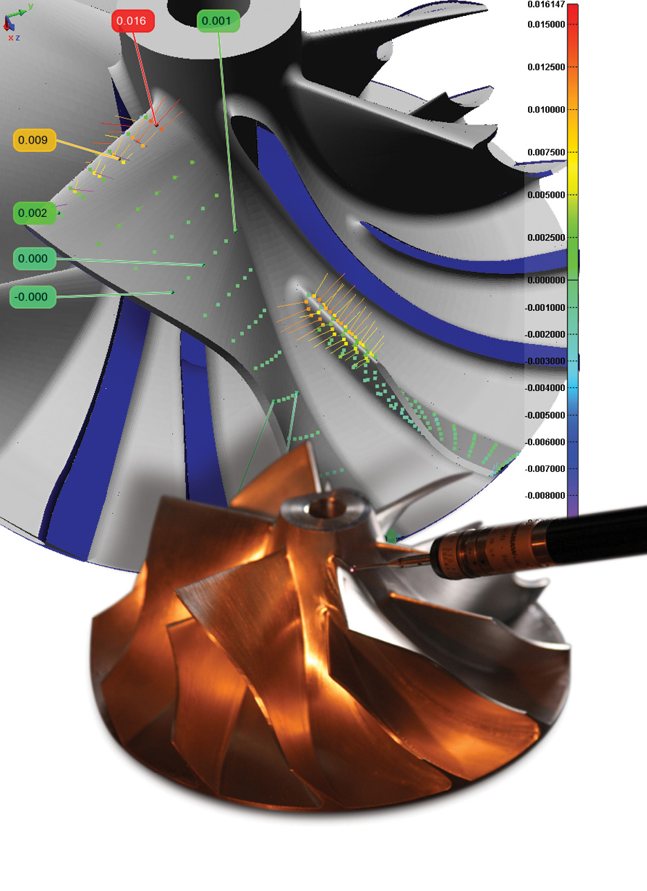
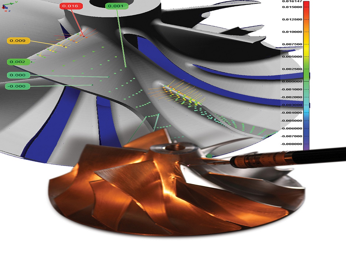
Best-fitting and inspection reporting of turbine wheel measurements acquired from a stationary CMM.
“Even if a job is running on a CMM, we can import the coordinates of contoured parts into PolyWorks|Inspector when we need more best-fitting or reporting options.” Steve Farentinos, President of Geoform
Selection is fairly clear-cut for software, too. Geoform uses conventional CMM software for long-running projects that justify CMM programming and for which a traditional, tabular inspection report is suitable. For other jobs on the CMMs and all PCMM work, PolyWorks is the tool of choice for Geoform. Farentinos said, “If we are using Faro arms, it’s a given that we’ll use PolyWorks|Inspector.” With plug-ins, Geoform can also run measurement sessions in PolyWorks|Inspector on manual CMMs and those operating under I++ servers.
The Benefits
Best-Fit Alignment
With traditional inspection methods, a handful of target points are used to define the coordinate system for all measurements, which locks down the dataset. So, a few measurements influence all subsequent results. To get more insight into a part, it can be beneficial to investigate the influence of the coordinate system by allowing it to “drift” away from the established target positions. This is one of many applications for best-fitting measurement datasets.
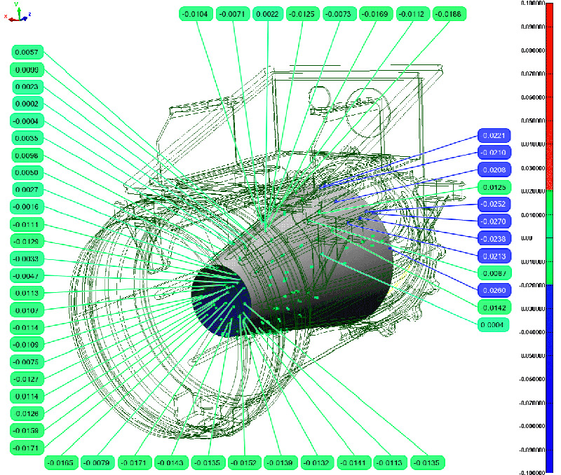
Inspection results for internal flow path (external surfaces displayed as wireframe).
Farentinos stressed, “If there’s best-fitting involved, we always run our measurements through PolyWorks|Inspector. This is one of its greatest strengths.”
Farentinos said, “When we’re inspecting a rough casting, for example, we might find some features out of tolerance when we’re set up to the datum targets. But our customer might be interested in knowing if there’s enough machining stock on the part if we deviate from the datum targets.” He continued, “It might simply be a matter of removing a small amount of material from one or more datum targets to salvage what would have been a scrap part. In these cases, we use PolyWorks|Inspector’s best-fitting capability to answer these questions.”
The measurement dataset, which may contain thousands or even millions of points, is aligned to the MBD-supplied CAD data to yield the “best fit” between the two. The alignment targets can be spread over the entire CAD model or zeroed in on a few features, such as casting datums. “This is great for castings and forgings that often have datum targets on drafted surfaces or where the datum has surface irregularities. The software uses lots of points to average out that variance. This gives a great fit and improves measurement accuracy,” said Farentinos.
Another alignment method that Geoform uses is “best-fit to tolerance zone.” Geoform requested this PolyWorks|Inspector™ tool in 2008, and assisted in its development, to minimize the number of features that are out of tolerance. This method combines the benefit of best-fitting with the advantage of finding a position for the scanned dataset that creates an acceptable part that would otherwise be rejected. Farentinos explained, “You simply select the option to best-fit to a tolerance zone, and the software reads the tolerance bands for the reference features. It then repositions the measurements between these bands. It tries to position the point set within tolerance, instead of minimizing the distance from nominal feature to digitized points.”
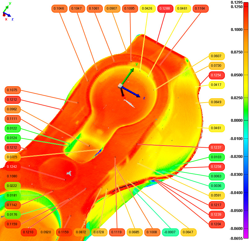
Color map inspection from laser scan data of an iron casting weighing nearly 1200 pounds.
Reporting
Whether measuring with a CMM or PCMM, Geoform opts for PolyWorks|Inspector when it needs to report more than tabular data. Farentinos said, “PolyWorks gives us a lot more freedom and a lot more reporting power.” Instead of page-after-page of tabular reports, PolyWorks|Inspector provides Geoform many options and many ways to produce visual, intuitive reporting.
One of the strongest points of PolyWorks is how easy it is to generate a report; especially multipage reports with color maps, tables, headers, and footers.
PolyWorks|Inspector enhances standard report formats, such as AS9102, with graphical documentation. “The inspection results are much better presented in PolyWorks and much easier to get at. One of its strongest points is how easy it is to generate a report; especially multi-page reports with color maps, tables, headers, and footers,” Farentinos said. “For MBD-type aerospace reports, we complete the AS9102 report and reference the graphical color maps generated by PolyWorks. This gives the customer something to look at in addition to the standard inspection report.”
Farentinos said, “It is really just drag-and-drop. You can make a report in a couple of minutes.” He backed up this statement with an example. “I’ve got an eleven-page report. I worked on it this morning. I started with the point cloud and in an hour and one-half I had a finished report. It really is that easy.”
Farentinos went on to describe inspection work was for a complex turbine wheel with many contours. He expressed how, yet again, PolyWorks|Inspector made the project simple. He noted, “With this type of project, we use the macro language in PolyWorks to automate some common commands. It’s great for reporting. We have one macro, for example, that exports XYZ data tables from a subset of a laser scan to provide supporting documentation for the standard inspection report. We can go from raw inspection data to complete report in 90 minutes.” This is one of many reasons that Geoform finds PolyWorks to be the best fit for its metrology work.
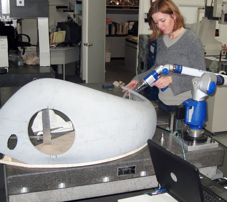
Inspecting a contoured automotive part with FARO arm.
