This article is written by Charles-Olivier Amyot . It is being re-produced here. To check-out to the original one, please refer to the link given below :-
“https://blog.trilion.com/structural-testing“
The use of an optical measurement system for structural proof testing, which measures deflection and strain data, can save valuable schedule time. In structural proof testing, traditional deflection measurements use physical contact Linear Variable Differential Transformers (LVDTs), which require labor-intensive mounting fixture fabrication that is set up around the test article to hold the sensors. It also requires an operator to adjust and validate each sensor. Therefore, significant cost savings were realized during a James Webb Space Telescope (JWST) bus structures test where an optical measurement system augmented the use of LVDTs to reduce test schedule time. These deflection measurements characterized the structure’s deformation and validated the theoretical finite element model.
This article is a summary and abbreviated version of a Northrop Grumman paper presented in March 2017 at the 30th Aerospace Testing Seminar by Andy Pokk and Chris Gurden. Approved for public release; NG 17-0278 dated 2/22/17.
OVERCOMING LVDT MAJOR DISADVANTAGES
Each sensor measures in a single axis and requires additional fixtures and sensors to acquire data in orthogonal axes. A measuring technique that uses high-resolution video cameras, 3D tracking/Data Acquisition System (DAS) software, and tracking targets for measuring deflection is an innovative solution to acquire 3-dimensional displacement information with reduced setup time. This video-measuring deflection technique is “non-contact,” where tracking targets are placed at key locations on the structural test article. The cameras are focused on the desired field of view (FOV). These tracking targets allow the collection of data in three axes versus a single axis. The output is real-time data recorded in a display of load versus deflection for the structural analyst to view during the mechanical proof testing process.
Shown in light blue in the four corners of the test article, which are tracked optically in 6-DoF.
At the top of the image, the black camera bar shows the position of the optical sensor aimed down and focused on the entire test article. The line-of-sight of the cameras and points monitored allowed the program to eliminate LVDTs.
ACHIEVING EQUIVALENT ACCURACY AND SAVING TIME
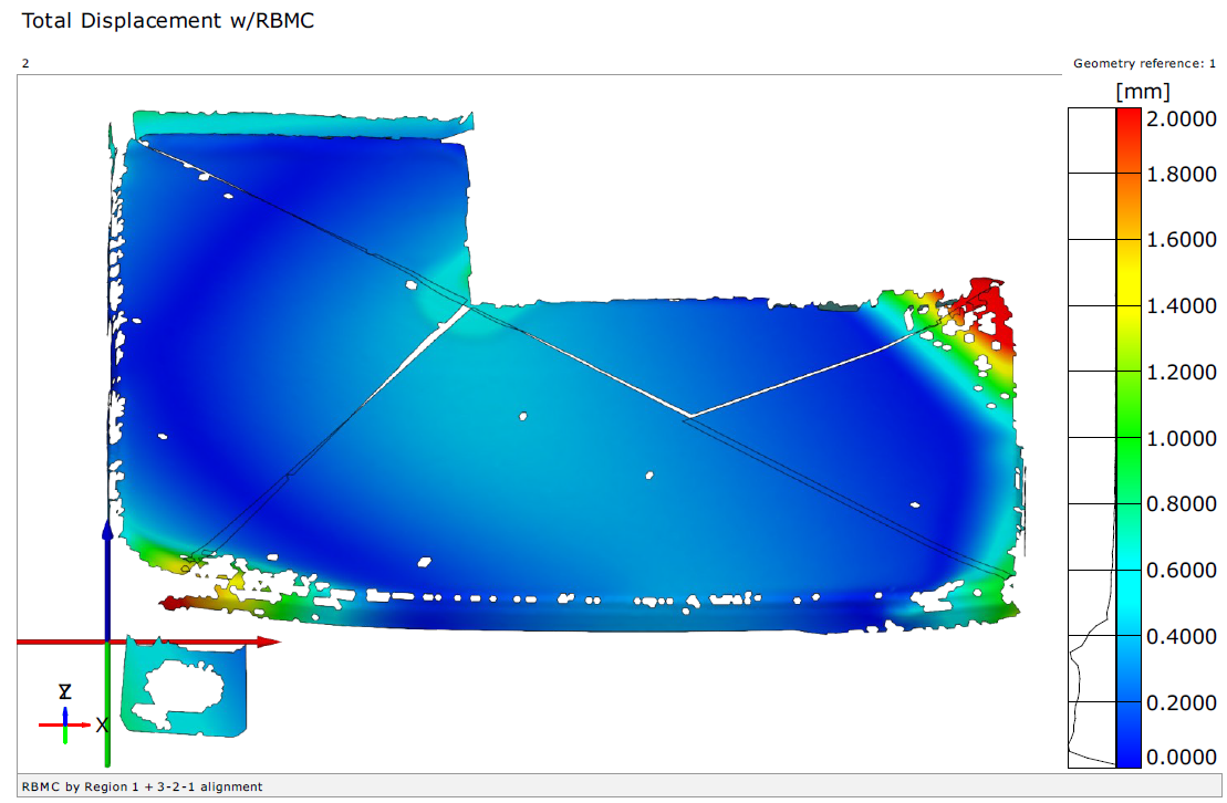
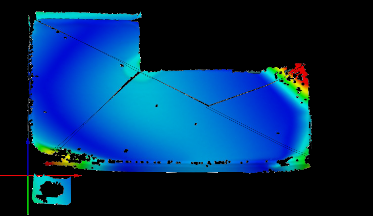
The optical measurement system displacement data was found to be equivalent to the LVDT data for the 10-foot FOV. A 25% schedule savings was realized using this technology for primary use on the bus testing. The additional off-bus panel and other associated tests added additional substantial cost savings. The targets being reusable throughout the test process and minimal cost just added to the cost savings for the JWST project. The elimination of most of the LVDTs was considered cost avoidance for the setup time and avoided any risk of having LVDT fixturing around the bus. The well-planned target strategy revealed deflections not anticipated.
The merging of load versus deflection data along with display saved the analyst time and
allowed more time for review. Since the optical measurement is non-contact and relies on an
unobstructed view, it works in certain situations where LVDTs do not work; for example, where LVDT fixturing is challenging or overextension may occur. The attractiveness of the non-contact capability allows for no applied force effect on the measurement area. The ability to replay a recording is an excellent visual tool for showing deflection envelops or vector fields across an area. For example, the system provides 3D coordinates and 3D deformation with in-plane and out-of-plane deflection vectors. With the 12 mega-pixels cameras, accuracies were between 0.5 and 1.5 mils depending on the FOV. Overall, the system provided a very rapid measurements process with full-field, real-time results, and wide-area coverage.

