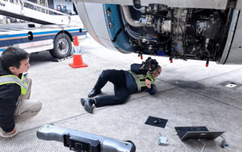
The axle processing machine needs to be inspected and straightened periodically in order to bend and deform the axle during processing. Traditionally, technicians used hand tools to inspect and straighten these machines, which was inefficient and prone to errors. The FreeScan Combo 3D scanner, combined with QUICKSURFACE software, offers a high-tech solution to streamline this process and improve accuracy.
Background
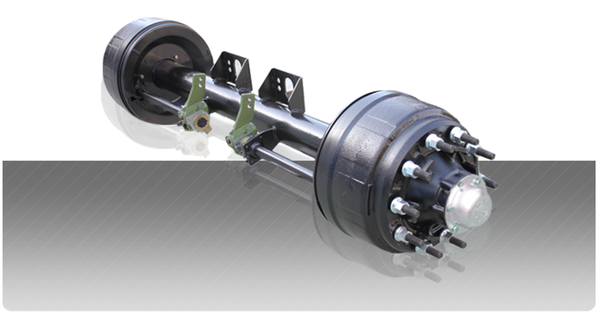
Axle is a central shaft for a rotating wheel or gear, essential for supporting the weight of the vehicle and enabling wheel rotation. Chucks and jigs from both sides of the machine tool will hold the shaft and rotate it during the machining process. In order to ensure that the machining machine runs smoothly and that the shafts do not bend or deform, it is important to ensure that the centers of the individual parts on the machine are matched. Therefore, technicians need to check the machine parts regularly.
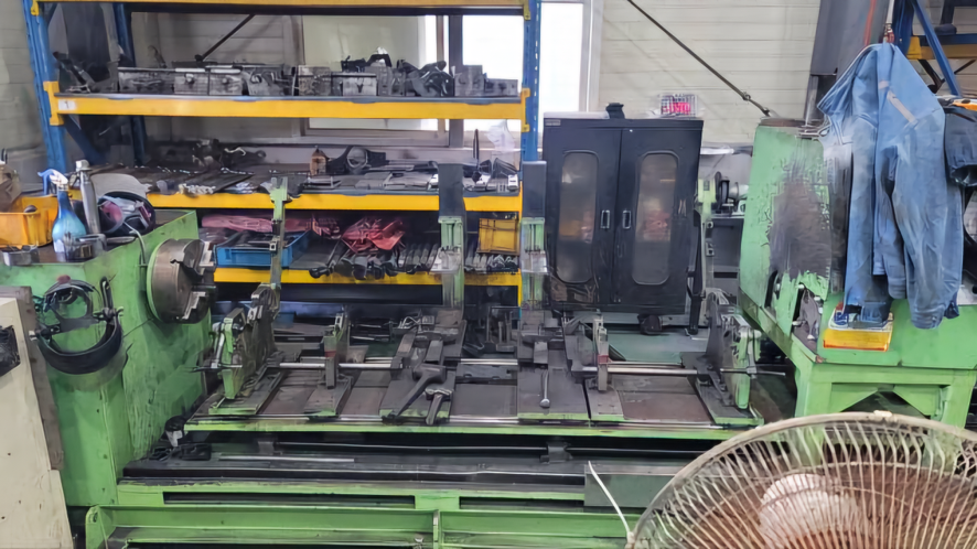
Methods of Axle Processing Machine Measurement
Traditionally, technicians manually check axle processing machines. This method was time-consuming and often inaccurate. Manual inspection also requires significant skill and experience, making it a challenging task.
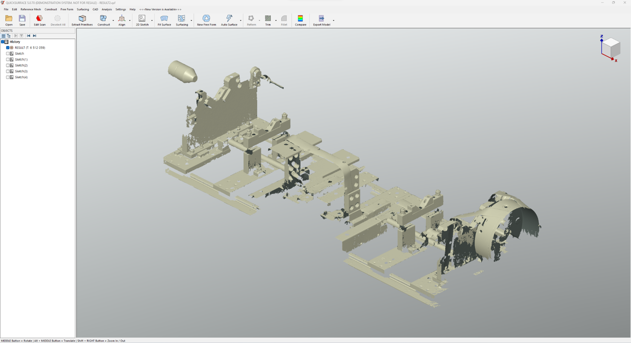
The SHINING 3D FreeScan Combo and QUICKSURFACE software offers a modern solution to the challenges of manual measurement. Technicians use the FreeScan Combo to capture scans of an axle processing machine and then import the scans into QUICKSURFACE software for measurement. According to the customer’s requirements, we checked the dimensions of several parts.
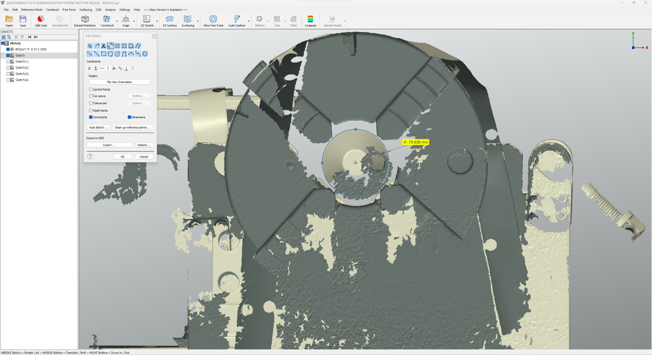
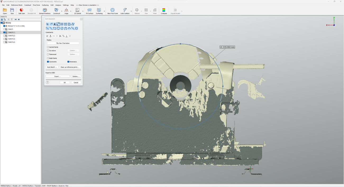
Using QUICKSURFACE’s 2D sketching feature, we created a circle on the rotary axis data to see the diameter dimensions of the rotary axis. Using the same method, we also obtained the diameter and dimensions of the chuck.
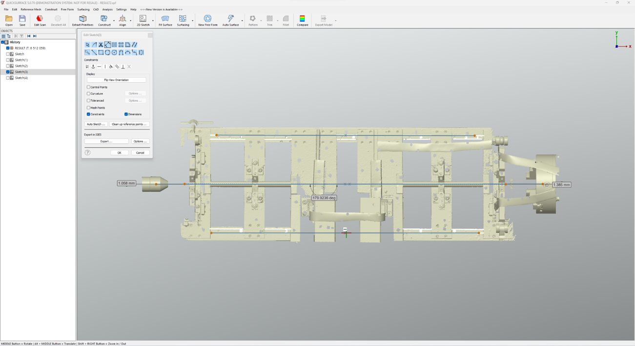
Connect the center of the rotary axis and the center of the chuck to obtain a straight line (solid line in the figure). Compare this solid line with the average line of the processing machine guide (dotted line in the figure). They form an angle of 0.0764 degrees, and the error at both ends is about 1 mm or so, 1.058 mm on the left and 1.385 mm on the right.
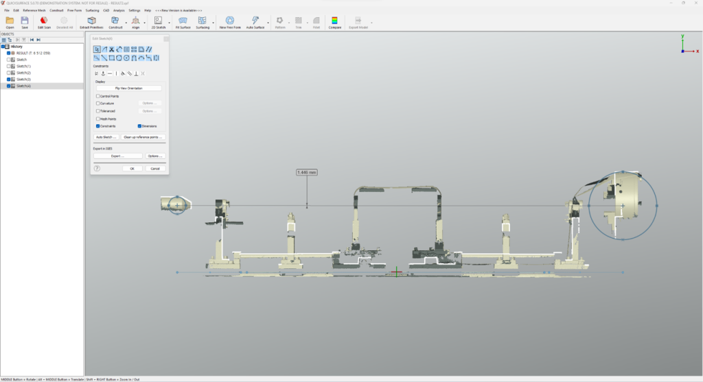
Measure the difference in height between the rotary shaft center point and the chuck center point. The shaft center point is higher than the chuck center point.
Significant benefits of 3D scanning
3D scanning technology has very clear advantages over manual measurement methods. This is demonstrated by the following:
Enhanced Accuracy: The 3D scanner captures highly detailed and precise scans, reducing the risk of human error in measurements. QUICKSURFACE provides in-depth analysis capabilities, allowing for accurate measurements.
Time Efficiency: 3D scanning and analyzing is significantly faster than manual methods, saving valuable time.
User-Friendly: The scanner and software is easy to use and requires less technical skill than traditional hand tools.
Conclusion
The combination of the FreeScan Combo 3D scanner and QUICKSURFACE software addresses the challenge of manual inspection by providing a faster, more accurate method for ensuring machine parts alignment.


