
This content was originally written and published by the AAT3D team on their website. Reproduced here from https://aat3d.com/in-process-measurement-of-die-mold-for-high-precision-manufacturing/
By Ray Karadayi
Applied Automation Technologies, Inc
Rochester Hills, USA
Abstract
The demand to manufacture precision parts at high quality and at a lower cost requires a better interface of metrological analysis within the manufacturing cycle. New advancements in the machine tool control systems and electronics allow complete dimensional measurement of parts where they are manufactured. Software developed for this purpose can perform quick setup and complete measurement of all geometrical and composite features. Direct feed-back methods enable automation of high-volume production of parts in an automated factory by adjusting manufacturing parameters with the results obtained by measurement cycles. Complete measurement and tolerance analysis are reported graphically and stored in a database for statistical analysis and forecasts. This paper discusses the results of several years of development for in-process adaptive manufacturing by using measurement software
1. INTRODUCTION
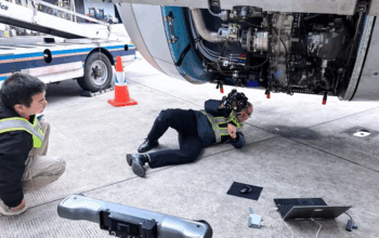
Manufacturing a high precision die is a long process that requires dimensional measurement at multiple phases. Traditionally, this is done by a Coordinate Measuring Machines located in a controlled environment. This requires removing the die from the machine where it is made to the quality control room where the CMM is located. This is a very expensive process and in most cases not practical. The use of portable arm machines and laser trackers allows measuring the die on the same machine. However, this is not as accurate and could interrupt machining time. The recent advances in machine tool technologies, probing systems, and software such as CappsNC1 allows measuring dies on the same machines where they are made. This paper discusses measuring dies and other large parts of the machine tools where they are made.
2. IN-PROCESS MEASUREMENT
In-process measurement of a part is measuring three-dimensional metrological characteristics of a part while the part is still located on the machine where it is being manufactured. This could be measuring locators and datum features of the part before any cutting process to calculate the exact position of the part for the cutting programs, or it could be measuring certain features between different operations of the cutting process for example to calculate tool wear or could be performed at the end of a manufacturing cycle to do a complete metrological analysis of the part to produce an inspection report.
In-process measurement is becoming more and more a method of utilizing the manufacturing machine similar to a CMM. Because the probe can be held in the machine’s tool magazine, the process can be performed as a part of an automatic manufacturing cycle.
3. PREPARING MACHINE FOR IN PROCESS
3.1 Probe
A special machine tool probe is used to take measurements of the part by a tactile measurement. These probes are designed to work in the harsh manufacturing environment of the machine tool and loaded directly to the spindle of the machine like a cutting tool. Probe signal is interfaced with the circuit of the machine tool controller to generate a 3D point at the exact location of the contact. Modern probes have an optical or a radio frequency interface to receive the signal from the probe. This eliminates additional wiring and enables the probe to be held in the tool magazine like a cutting tool.

3.2 Probe types
The most common probes used today are kinematic and strain gage probes. Kinematic probes have a mechanism within the probe body that generates a trigger signal which makes it more precise for uni-directional measurements along X, Y, or Z axes. However, they are also very repeatable allowing a calibration process developed within the measurement software to make it accurate. Figure 2a shows the non-uniform trigger point of such probe and in the 2b calibration screen of the measurement software that compensates for it.

Figure 2: Non-uniform trigger plot & calibrration screen
3.3 Probe as a tool
Since a measurement probe in a machine tool is used to measure features of the part in relation to a machine’s coordinate frame and other cutting tools used to make the part, it must be defined precisely in relation to the whole system. To achieve this, a number of characteristics of the probe must be calibrated to minimize any errors being introduced into the system. Figure-3 shows characteristics of a probe used on a 5 axis machine.

The characteristics that need to be calibrated are:
a) Run-out or offset at the tip center
b) Effective radius
c) Effective length from the head rotation center
d) Directional errors for kinematic probes
e) Offset errors due to 5 axis head misalignments
The measuring software utilized must-have tools to perform these calibrations automatically and in relation to other cutting tools in order to relate the measurement data back to the manufacturing process.
4. MACHINE GEOMETRY ERRORS
In order to assure the quality of the measurement data and minimize the measurement uncertainty of the system, the machine’s own geometric errors must be taken into consideration. Especially for machines producing large dies would be more prone to changes in the geometry due to forces applied during the manufacturing process. Unlike a CMM which is usually kept in a controlled environment and works with very small forces that would alter its geometry, a machine tool works with large cutting forces and at high non-uniform temperatures. For this reason, calibration and verification methods that could be quickly used must be employed.
4.1 Machine tool calibration
A 3 axes machine tool would have 21 different sources of geometry errors that would affect the accuracy of the system. Machine tools with more degree of freedoms such as 5 axes tools with rotating heads or tables or multi-axes mixed configurations like mill-turns would have additional sources of errors. Typically, a machine tool is manufactured to be accurate mechanically. In some cases, any errors left are measured by a laser and corrected within the controller of the machine. This usually is a lengthy process which is not done frequently and needs expensive equipment such as a laser interferometer.
A more practical method would be using special gages that could be measured quickly and automatically to determine dominant errors of the machine tool. A ball bar system called Tetra2 gage is such a device that could be used on a machine tool by measuring 4 spheres as seen in Figure 4.

By running a program to measure the spheres on this gage, machine tools’ geometrical errors within the volume of the gage could be very quickly calculated. These errors are then used to compensate within the measuring software or uploaded to the controller to correct the motion for the cutting process.
4.2 Machine tool verification
In most cases, measuring a gage like a tetra is enough to determine if the machine’s accuracy is still within an acceptable range. This process would give the confidence that the machine geometry is still within an acceptable range and provide traceability of measurement data to a gage. This also provides data to schedule a full calibration.
5. MEASUREMENT PROCESS
The primary function of the machine tool is producing a part by cutting off material from a row block or a cast material. For this reason, the measurement process must take as little time as possible. Measurement programs are created by offline software that could generate machine codes without taking any time from the machine. These programs are then uploaded to the controller of the machine tool and executed by an operator or automatically by a logic process flow. Figure 5 shows the block diagram of the interface data flow between the measurement software and machine tool.

5.1 Program development
Measurement programs are developed offline by using specialized software with a graphical user interface. These programs could be as simple as measuring a datum feature or could be a complex metrology analysis program that measures many different characteristics that need to be controlled. CappsNC is an example of such software used for in-process measurement. In this software, a virtual machine modeling is used to accurately represent a machine tool in order to automate many of the programmings such as automatic path generation with collision avoidance and calculating optimum joint parameters for a multi-axes machine. The developed program is a complete measurement program that includes not only the machines tool path but also all the information about generating a metrology report as well as feedback commands to the machine for performing work offset or tool compensation
5.2 Post-processing
The offline developed measurement program which is in DMIS format for the CappsNC case would need to be post-processed to a machine code that the controller can understand and execute. The post-processing is done specifically to the machine tools controller using the actual command set which the controller would understand.
The post-processed code is uploaded directly to the machine tool controller from the software. Once in the controller, it can be listed as a part of the machine tools other programs like the cutting programs or macros. The measuring program is executed automatically as a part of a batch program or could be selected and manually executed by an operator.
5.3 Program execution
The program selected on the controller automatically invokes the measuring software which runs on a computer directly connected with the machine tool controller. This initiates the measuring program to execute in synchronization with the machine tool. The measurement data received as points with its x,y,z coordinates are immediately processed by the measuring program previously developed and results are generated and displayed. Any programmed instructions that would generate feedback to update parameters on the controller are executed as the program is being executed. This allows autonomous and adaptive manufacturing within the process cycle.
6. ALIGNMENTS AND WORK OFFSETS
6.1 Work offsets
A machine tool cutting program is also developed offline usually on a CAM system by using the CAD model of the part to be created. This program is created at an assumed coordinate system that would have to be created on the machine tool as a work offset. Different machine tools have different levels of capabilities for creating and managing these work offsets. In most cases, work offsets are simply an X Y Z translation of the part origin to where it will be located on the machine.
For large parts such as dies, to achieve a simple work offset with just a translation could be very difficult. For this to work, the part would have to be precisely aligned along the axes of the machine tool. To avoid this long and costly process, the measurement software could generate a 6 degree of freedom coordinate system that could be transferred to the controller as an extended work offset.
6.2 Developing alignment programs
An alignment is a representation of a part’s exact position and orientation and 3D workspace. It holds information representing the 6 degrees of freedom of a part with 3 translations and 3 rotations. The Euler representation of an alignment would be the translations along X Y Z and rotations about each axis with A B C. Several methods can be used to create this alignment based on the requirement and availability of features on the part:
6.2.1 Setup with datum features
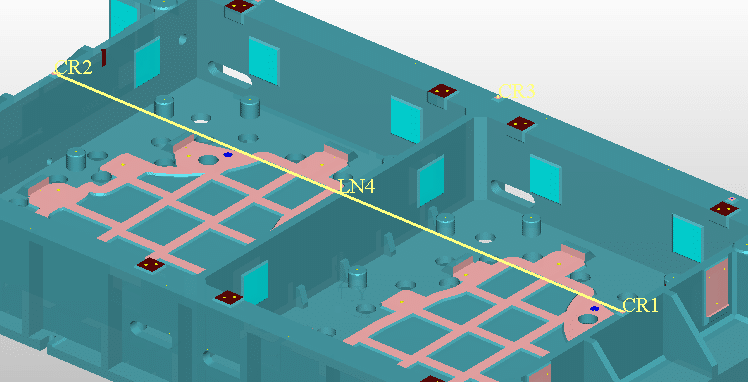
A common method of aligning a die is by measuring two datum features and creating the alignment. For example, a plane represented by the Z-axis of the machine, and a line constructed by using two circles can be used to create a complete alignment as seen in Figure 6. This alignment locates a rotation of the die from its intended direction and locates the position precisely with the datum circle.

6.2.2 Setup with tooling balls
Another common method of aligning a large part such as a die is using tooling balls. By attaching 3 or more tooling balls around the part, a reference frame can be created. A program can be very quickly generated to measure these tooling balls and the measurement software will create a relationship with its intended locations. This allows a very quick setup of the die even when there is a large misalignment of the part axis from the machine directions. Figure 7 shows such a setup.

6.2.3 Advanced alignment methods
Sometimes a more complex alignment method such as best fitting all the surface measurements to its CAD mathematical definition is necessary. For example, a cast part with many irregular sculptured surfaces and no measurable geometrical feature can be aligned by measuring several points and best fitting them to the surface definitions. Additional constraints are used to avoid undercutting of the part by leaving a positive stock.
7. MEASUREMENT METHODS
Several measurement methods can be used depending on the needs and limitations. The most common and feasible method is developing a complete measuring program offline and executing it on the machine. However, this would require at least a close starting alignment of the part which could be difficult and time-consuming especially for large parts. In this case, manually initiated interactive macros can also be developed.
7.1 Interactive measurement macros
A custom measurement macro can be quickly generated offline by using the CAD model of the part. For example, a single sphere measurement program can be generated to measure the tooling balls. In this case, the user would simply place the die at any location without worrying about the precise orientation of the part. The probe is then moved by using the jog feature of the machine tool above the tooling ball that needs to be measured. By executing this macro, the program would drive the machine to measure this sphere, and the measuring software would calculate and create an image on its screen. By using this method, any number of spheres or other features could be measured one at a time or in groups very quickly. Figure 8 shows an image of such a measurement of a tooling ball.

Another useful application for an interactive macro would be to compare the surfaces being machined to its intended CAD models. In this case, a macro is developed to measure a single or multiple points in an area. This macro is then executed at the desired location of the die where a comparison data needs to be generated. By manually moving the machine to these desired areas and executing this macro, the software will automatically compare these points to the CAD model generating a measurement report. Important benefit in this method is that the operator, not the programmer decides which locations to be measured on the die based on the special circumstances that was encountered. Still the data is compared and reported against the CAD model by the measurement software.

7.2 Automatic program execution
By using the software in offline mode without connecting to the machine, an inspection program can be developed that would be executed as a complete measurement program. This program can be simulated both for correctness in machine motion and the report that will be generated before attempting to run on the machine. Once a machine code is produced by post-processing, the measurement software connects to the machine with a live interface collecting the measurement data. The measurement data is used to synchronize with the measurement instructions to perform the tasks already programmed. In an automatic program, the following tasks can be achieved:
In an automatic program, the following tasks can be achieved:
• Measure points on any surface orientations
• Measure and analyze surface forms and profiles
• Measure curves along selected sections
• Measure any geometric features such as planes, lines, circles, sphere, cones
• Construct features by methods of intersection, projections, and others.
• Calculate coordinate systems
• Generate tolerance and dimensioning reports such as distance & true positions.
• Feedback work offset data to the controller
• Update actual tool offsets to the controller
• Generate measurement reports with numerical and graphical methods
• Perform Statistical calculations
7.3 Reverse engineering
Another useful method of inspecting dies on a machine tool is to measure curve profiles at selected cross-sections. This is done by generating a program that follows an unknown profile by adaptively controlling the machine motion. Once several curve profiles are measured, a surface can be generated and displayed in the software. This data can be exported to a CAD/CAM system to generate a precise cutting program. This is a very useful method especially while fixing dies or other parts by adding material.
8. SUMMARY
In-process measurement is used in multiple phases of die manufacturing. By measuring the datum features, a die is precisely located on the machine reducing the expense of die setup times. The coordinate systems calculated are uploaded to the controller which many modern controllers can use to mathematically adapt the cutting programs. A simple measurement of surface locations could help determine the amount of stock available for cutting. A cutting program that is mistakenly generated for the wrong surface or with the wrong thickness offsets could be determined before any damage is done on the die. Finally, a complete measurement report could be generated without having to move the die from the machine. All of these features not only reduce the cost of manufacturing a die but also assures manufacturing a die that meets all requirements.
To know more, please check AAT3D.