
To guarantee accurate machining for castings, the machining allowance must be closely controlled. The remaining components from the prior operation are challenging to remove due to an inadequate machining allowance.
An excessive allowance will increase the burden of the machine and the amount of materials, equipment, and energy used.
Scantech is a high-tech 3D scanner producer that sells items including 3D body scanners, automated 3D measuring systems, and 3D laser scanners. We are committed to enhancing your company through the provision of effective 3D solutions.
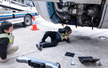
In this application story, we’ll demonstrate how to record a large-scale casting’s full-field data and determine its allowance for additional machining. TrackScan-P, a non-contact 3D scanner for huge objects, is the technology we employ.
Optimization of Casting Machining
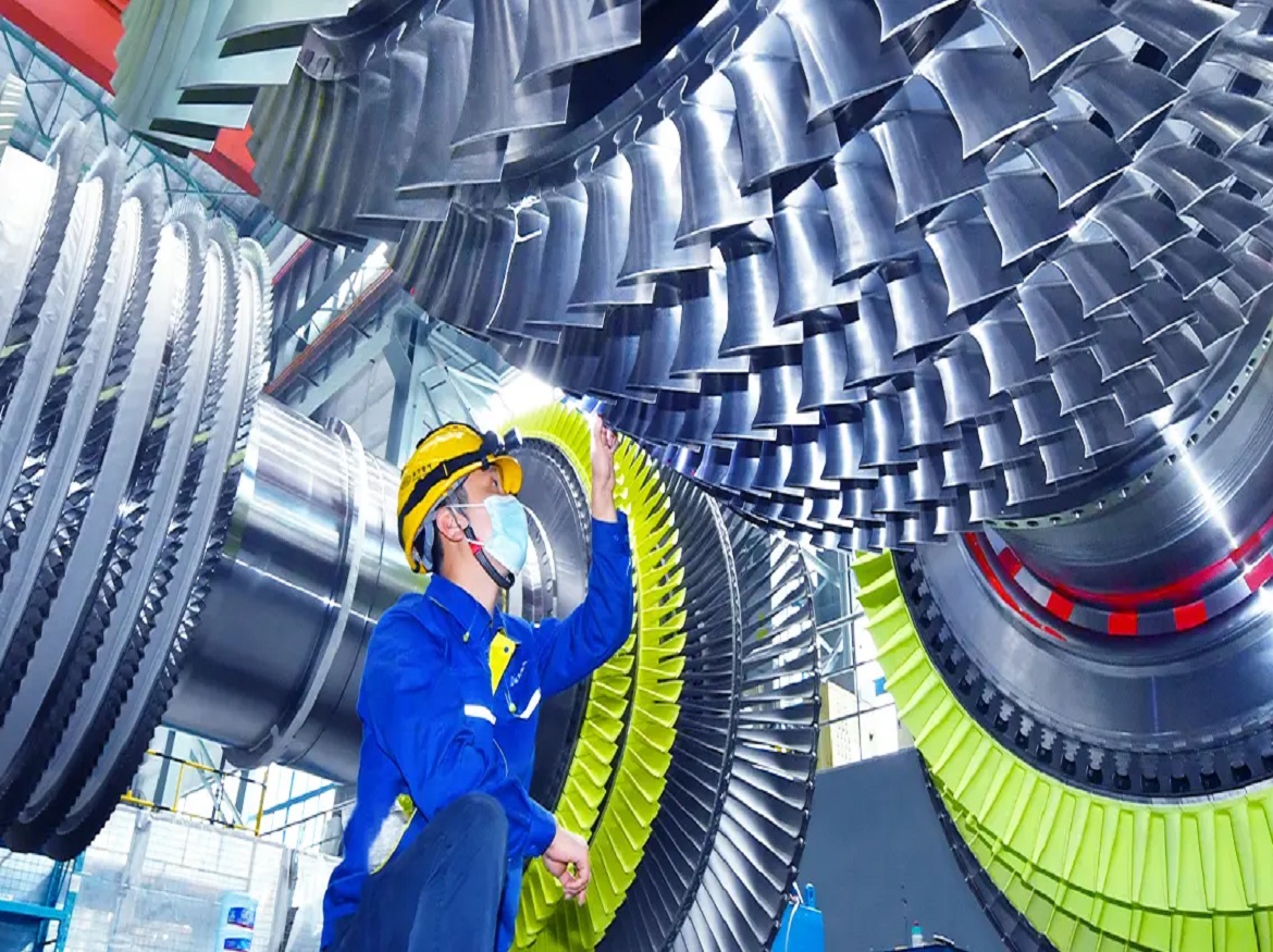
A high-tech company called Dongfang Turbine Co., Ltd. of Dongfang Electric Corporation specializes in the development, design, and production of big power station machinery.
Coal-fired steam turbines, nuclear steam turbines, gas turbines, turbine retrofitting and service, industrial turbines, innovative materials, and new energy products are among the company’s offerings.
The client was searching for methods to enhance casting machining. To determine whether there is enough room for more machining, they 3D scan the casting and compare it to the CAD model.
If there is no allowance at some surfaces, it is necessary to determine whether fitting can be done to ensure that these surfaces can later be machined. Customers must identify the places that are thinner than the allowance and calculate the cost of repair welding if the first method doesn’t work.
The data gathered will be used as a guide for virtual marking and identifying the machined datum for the CNC machine after the inspection.
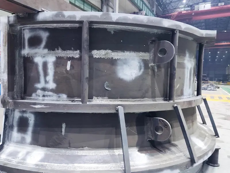
In this instance, the casting is an exhaust hood for steam. With a diameter of roughly 6 meters, it is sizeable. Full-field scanning must be done in order to establish the marking for the machining datum and the marking for 20 holes.
Pain Points of Traditional Manual Marking
The client used to manually mark castings using empirical estimation to determine whether the allowance was sufficient and to identify the datum.
This time-honored, manual approach is ineffective and fails to identify the ideal data. The operators must restart and locate a new datum each time they change the part’s position, which takes time.
Users can determine the precise allowance of parts for marking via virtual marking in an accurate 3D model. Manual marking is substantially less accurate than virtual marking.
As a result, some qualified items might be rejected as unqualified or flawed, which would raise the price of production.
How 3D Scanning Help in Casting Manufacturing
The business turned to Scantech for assistance in determining the allowance, improving marking, and speeding up machining for casting in an effort to save cycle time.
The steps that follow demonstrate how Scantech’s 3D solution assisted with this project.
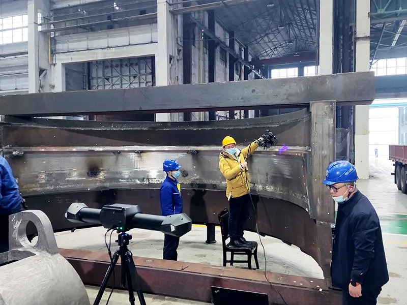
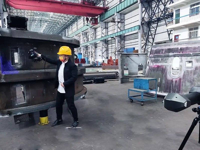
Step 1: Scan (about 1 hour)
The engineer scanned the casting’s full-field data using the optical tracking 3D scanner TrackScan-P to create the casting’s actual 3D model.
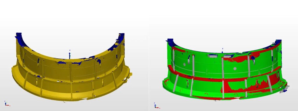
Step 2: Comparative analysis (about 10 minutes)
They were able to pinpoint casting irregularities because of the data that was collected. The engineer rapidly checked the scan data with the CAD model, then used 3D software to analyze the results:
- Check whether there is a sufficient allowance;
- For the areas where allowance was sufficient, the data was used to locate the optimal machined datum.
- For the areas where allowance was insufficient, they located the areas that needed to be repaired and identified the amount of repair welding.
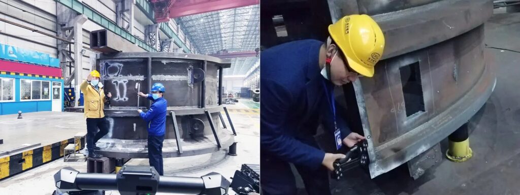
Step 3: Marking (about 2 hours)
Before they drew lines on the castings, they used the software to simulate the marking. The customer was able to calculate the marking location precisely and identify any potential issues as a result. Based on the analysis, the engineer marked the casting and the holes that needed to be treated.
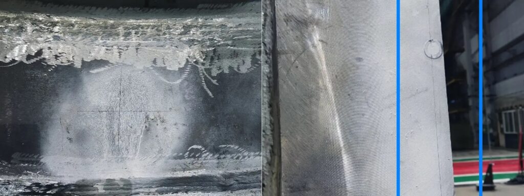
Step 4: Machining
Establish accurate data for machining as well as the positions of holes.
Features of Scantech’s 3D solution
The novel blue-and-red laser scanning-engineered 3D laser measurement scanner and sticker-free optical tracker make up Scantech’s optical measuring system TrackScan-P.
The technology measures the real geometry of the blank, replacing traditional marking and ensuring adequate machining allowance throughout production. Modifying the cutting path according to the data collected, it creates the data foundation for adaptive machining.
Ergonomic Design of 3D Scanner
- The portable 3D scanner can scan the part from any direction you want, which is easy to operate.
- The 3D scanner is built onto a spherical frame, which offers an even stress distribution. The markers placed over this soccer-like frame enable E-Track to position the 3D scanner in all directions.
- It’s made of aerospace fiber so it is lightweight. Due to its ergonomic design, the 3D scanner allows users to scan for a long scanning session with minimal wrist fatigue.
- It is seldom affected by temperatures and ensures steady performance.
Practice-oriented Design of E-Track
- The E-Tracker features a dual-camera system with a distance of 900 mm between cameras, which allows large-volume tracking.
- Thanks to the dynamic tracking of E-Track (the optical tacker of the TrackScan-P measurement system), it can identify the position of the 3D scanner in relation to that of the part freely, which greatly improves the non-contact 3D scanning efficiency. It also boasts a smooth performance as it can be operated regardless of vibrations.
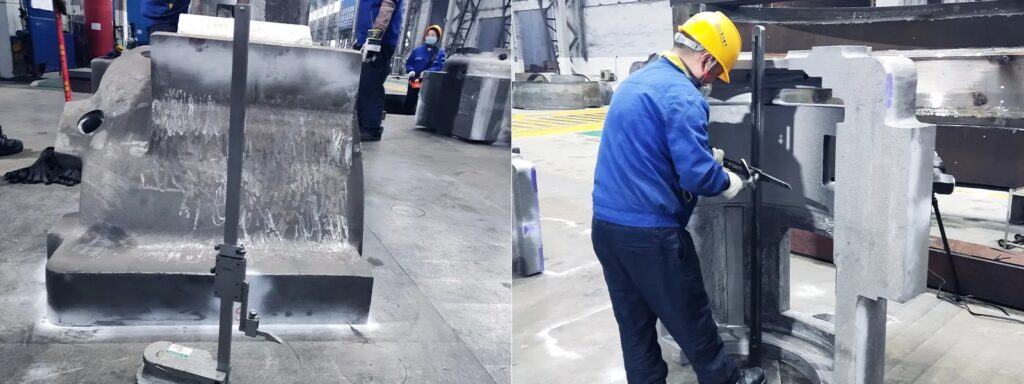
Wireless and Portable CMM T-Probe
The Wireless T-Probe has probes of various lengths. They may swiftly get high-precision 3D data by doing contact measurements with a portable T-Probe. It implies that they can simply probe a mark to determine its accuracy.
Project Significance
- The 3D laser scanner can scan the full-field data of the parts. Users can analyze the machining allowance quickly and set up the machining according to which improves production efficiency.
- The solution helps to identify the area where repair welding is needed, reducing the defective rate of products and decreasing the costs.
- The efficiency of marking is enhanced by virtual marking in the software.
- The machined datum is adjusted according to the analysis to ensure every surface to be machines has a sufficient allowance. It contributes to reducing the reject ratio.
- It was beneficial for manufacturers to ensure the parts machines could conform to the specifications required.
Click on the following link Metrologically Speaking to read more such blogs about the Metrology Industry.