Most gages on the shop floor provide a specified level of accuracy in conditions for which they were designed. But in the production environment, where tight tolerances are a way of life, it’s critical to think about gaging requirements before putting instruments out there and possibly having them not meet expectations.
In short, if you’re trying to measure to microns, every micron counts. Thus, it is very important to ensure that proper thought is given to the gaging process. Ask yourself, “Where may I lose a micron here or there that I should be accounting for, and how do I prevent that from happening?”
When starting on the path of improved gaging performance, you’ll see how quickly you can pick up some microns, but also find that as you increase performance, the microns get harder to find. Case in point, a manufacturer recently came to us with a requirement to inspect a wide variety of hole sizes on a line of valve bodies.
Some of the relevant parameters for this gaging situation included:
• Throughput. With literally hundreds of thousands of parts to measure, inspection had to be fast and foolproof.
• Output. The manufacturer required the capability of automatically collecting data for SPC.
• Ease of Use. The parts being gaged were large, so the gage had to come to the parts, not vice versa.
• Accuracy. Most hole tolerances were ±25 µm, but some were as tight as ±12 µm.
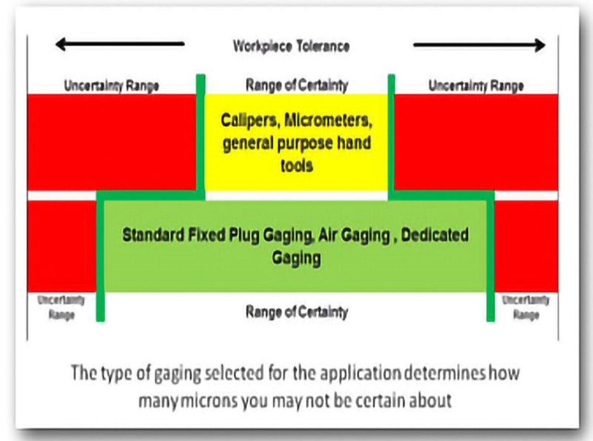
Hand instruments, such as calipers and micrometers, are important tools used in many places in the shop. But while versatile and quick, they just didn’t have the performance required for this particular application: they simply used too many microns of error.
The next step up in performance, adjustable bore gaging, wouldn’t do the job either. While the adjustable bore gage had the flexibility to cover a large range of hole sizes, it was rejected because of the time consuming operation of sweeping through the part, and a high skill requirement for the operator.
The manufacturer specified a GR&R (gage repeatability and reproducibility) requirement of 20% or better on holes with tolerances of ±25 µm. This meant that the gaging system had to perform to 4 µm or better. This requirement was met using standard gage plugs, and standard digital indicators with resolution of 1 µm: the GR&R achieved with this setup was less than 16%.
On holes with tolerances of ±15 µm and ±10 µm, however, the manufacturer required a GR&R of 10%, which translated to gaging system performance of 1 µm. Given the other parameters of the application, mechanical plug gages remained the only practical approach, so we had to find a way to stop the flow of lost microns to “squeeze” more accuracy out of the situation.
Plug gages are typically engineered for 50 µm of material clearance in the holes they are designed to measure, to accommodate undersize holes and to ease insertion. But the greater the clearance, the greater the amount of centralizing error. This is when the gage measures a chord of the circle, and not its true diameter. By reducing the designed clearance, centralizing error can be minimized, thus saving a few parts of a micron, albeit with some tradeoff against ease of insertion.
We engineered a special set of plug gages, with minimum material clearance of 15 µm. The standard digital indicators were also replaced with high-resolution units, capable of 0.5 µm resolution. This combination satisfied the requirements, generating a GR&R of less than 8.5%.
Remember SWIPE? This acronym stands for the five categories of gaging variables: Standard (i.e., the master); Workpiece; Instrument (i.e., the gage); Personnel; and Environment. In the case of the valve body manufacturer, we tweaked the instrument, thus reducing one source of gaging variability. We reduced a second source by providing higher-quality masters for these gages. If throughput had not been such a high priority, we might have also considered altering the environment where inspection was performed, or providing more training to personnel. If portability hadn’t been an issue, then the solution might have been a different instrument altogether.
The five categories of gaging variables encompass dozens of specific factors. (For example, within the category of Workpiece, there are variables of surface finish and part geometry that may influence dimensional readings.) To squeeze more accuracy out of a gaging situation, look for opportunities to reduce or eliminate one or more of these factors, and in the end those lost microns will be used in improved gaging accuracy, not dropped on the floor somewhere.
The type of gaging selected for the application determines how much of the tolerance zone is used for production as opposed to being lost because of poor gage performance.


