The below article has been written by Krista Dulon and reproduced from the given link :
“https://www.iter.org/newsline/284/1720”
There are carefully laid plans, and then there’s reality.
In the world of CATIA design models, the alignment of the ITER in-vessel components such as the blanket will proceed smoothly, without variances or deviation to trouble the horizon. Onto the nine welded sectors of the vacuum vessel, 440 blanket modules will be attached just so, respectful of tolerances of approximately 10 mm globally and nominal gap requirements between adjacent modules (both vertically and horizontally) of +/- 4 mm.
But engineers know that variances from design parameters will occur during manufacturing and construction. Weld shrinkage during vacuum vessel assembly will introduce variation, for example, and as a result the as-built picture of the vacuum vessel will differ from nominal models … with repercussions for all the assembly tasks that follow.

ITER’s in-vessel components have thus been designed to be adjustable. Manufactured in plants around the world and shipped to ITER, several thousand components will be customized during assembly to achieve the demanding tolerances allocated to in-vessel systems. For the blanket, composed of massive steel shield blocks that carry the plasma-facing first wall panels, alignment will be achieved by customizing approximately 4,000 interfacing components.
Central to identifying the variances—and defining customization requirements—are sophisticated optical metrology techniques.
“To have first-wall panels aligned within a relative step tolerance of 5 mm, the shield blocks must first be precisely installed,” says David Wilson, responsible officer for alignment and metrology for ITER. Each of the 440 blanket shield blocks will be bolted in four positions to the vacuum vessel wall. “Our challenge will be to machine the shield blocks’ customizable components —the flexible cartridges (which house the bolts) and the key pads—so that together they compensate for variation in the vacuum vessel.”

Metrology engineers will begin by surveying the as-built geometry of the vacuum vessel and comparing the results to nominal CAD models to determine variances to be compensated via the shield block interfaces.
To do so, the four cartridges from every shield block—1,760 in all—will be positioned by hand in their corresponding housings on the vacuum vessel. Identifiable through coded targets, they will aid the metrology software to make sense of a multitude of images taken by photogrammetry cameras. Thousands of other retroreflective metrology targets—over 20,000—will be distributed on the surface of the cartridges and keys so that viewing cameras are able to identify the axis of each cartridge, the planes that interface with the shield block components and even the rotation of the screwed-in components that, once machined, must be returned to the same location.
“It’s not simple,” says David. “But by querying the position and orientation of the cartridges and keys against corresponding interface coordinate frames on the shield blocks, we will be able to determine customization parameters for cartridges and key pads. How much material needs to be removed? What adjustments should be made in the surface plane or height? What location and angle for the access hole for the bolt that will fix the shield block to the vacuum vessel wall?”
The shield block cartridges and key pads will then be sent off site for customization.
“We know how the complete process will work,” says David, who works closely with other colleagues from Assembly and Operation. “But as a proof-of-principle, we conducted a trial for one complete blanket assembly last year. On a prototype built by the UK firm AMEC —complete with pre-built vacuum vessel interfaces—we confirmed the steps and feasibility of the blanket alignment through five complete iterations.”
Metrology surveys will be conducted at every stage of the in-vessel component assembly process. Once machined, the cartridges will be re-surveyed in their in-vessel position to qualify the process. Another survey will be carried out after the shield blocks are installed and still another following the assembly of the first-wall panels.
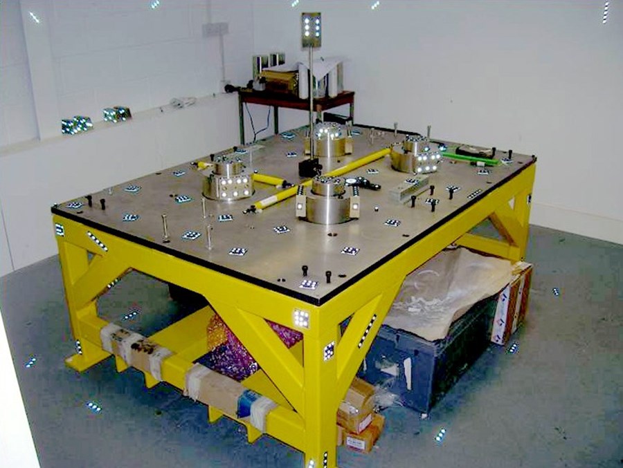
“We have established the flow chart of events, from surveying the as-built vacuum vessel to determining customization parameters to evaluating the alignment of components at every stage,” says David. “And we have just chosen a contractor to study the survey requirements for in-vessel component interfaces and develop a measurement scheme to meet them. Alignment tolerances are very demanding and therefore the measurement system selected must by extremely robust and accurate.”
The twelve-month in-vessel survey development contract signed in October with G2 Metric (Toulouse, France) includes the definition of camera locations and positioning strategy, online process monitoring, target designs, data alignment processes, analysis and reporting, and customization definition. As part of this contract, software shall be developed to manage the complete process from receipt of survey data through to the delivery of customization parameters.
“This is an important step for metrological processes,” concludes David. “Other in-vessel components will require similar surveying and customization as part of their assembly process and we will certainly learn from the development work accomplished for the blanket.”
NOTE :-
The ITER Dimensional Metrology Handbook (DMH) has been prepared to supplement Project Requirements documents in providing information on dimensional metrology for the ITER Organization and the Domestic Agencies. It explains how Alignment and Metrology (A&M) classifications are determined and details the requirements to be set in place for dimensional control.
Infrastructure subjects such as survey networks and datum evolutions are discussed with a focus on construction activities in the Tokamak Pit and adjacent galleries.
The application of controlled processes and best practice techniques are key elements within the Handbook, which aims to provide significant guidance to its readership. Measurement uncertainty, scale adjustments, instrument controls and component targeting are just some of the topics covered when discussing the control process for both on and off-site activities.


