The background to this is a natural physical phenomenon: most materials expand when heated and contract again when cooled. The aim of a test procedure in production metrology is to determine the actual size of a workpiece. Based on the first ISO standard 1 from 1931, this temperature is automatically assumed to be 20 °Celsius. However, only a few measuring systems monitor the temperature of the workpiece or even attempt to correct the measured values.
Numerous factors for thermal size deviations
Many quality managers assume that any thermally induced size deviation of the workpiece to be measured is compensated for by a corresponding expansion of the measuring device and the setting standards: All components expand or contract to the same extent, so that in the end the result is correct. In reality, however, this is not the case. The measuring device, setting master and workpiece – the three hardware components of a measuring system – can be made of different materials, so that they also behave differently when exposed to heat – even if they all have the same temperature. However, the temperature of the individual components can actually differ from one another:
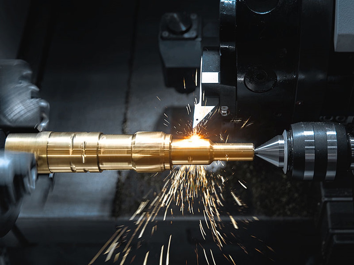
- Workpieces that have just come out of a dry machining process can be several degrees warmer and remain so for hours.
- Components that have been processed with coolant can be cooler.
- The measuring device or the setting master can stand on a workbench in direct sunlight or under a heating or cooling valve and therefore be warmer or cooler.
- Temperature stratification in a room can lead to temperature differences between components near the floor and those on a high shelf.
- The relative mass of the components can also make a difference: for example, a motor block takes longer than a bore plug gage to equalize to the ambient temperature.
In certain cases, the thermal fluctuations of the measuring device and the workpiece can also have the opposite effect, increasing the measurement error rather than compensating for it. For example, high temperatures cause the contacts of bore gages to become longer. This in turn causes the inside diameter to be smaller than actually measured. On the other hand, the inside diameter of a thin-walled part becomes larger at higher temperatures.
Environmental control for measuring laboratories
Some manufacturing companies try to solve this problem by controlling the room environment. This includes, for example, installing sophisticated heating, ventilation and air conditioning (HVAC) controls or making structural changes. These measures are effective in measuring laboratories, but not in machine halls. These buildings are too large, contain too many heat-generating devices or machines and therefore too many variables overall.
Solution from Mahr
It is more effective to measure the temperature of the measuring device, the setting master and the workpiece and to compensate for the thermal fluctuations on the basis of the known expansion coefficients. Mahr offers the right solution for this application: For the Millimar product family, it consists of a combination of the Millimar Cockpit software with a commercially available external temperature measuring device. Two sensors are installed in the measuring setup: one for measuring the temperature of the setting master and one for measuring the temperature of the workpiece. The Mahr software can now be programmed for different expansion coefficients of the various components. It records the results and calculates a temperature-compensated measurement result. Users can also specify additional compensation factors in the Mahr software, such as unusual geometries or differences between the surface and internal temperatures of a workpiece. This provides customers with a highly efficient solution: a temperature compensation system of this type generally reduces thermally induced measurement errors by 90 to 95 percent.
Would you like more information about the Millimar Cockpit software? Then take a look at their website.


