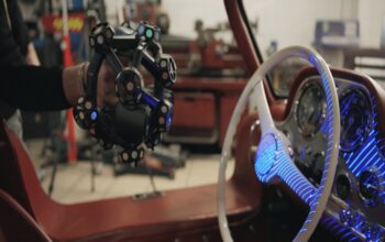


Since its founding in 1962, OCM has amassed and utilized a tonne of equipment, for which the technical blueprints are no longer available. With the Kreon measuring arm with a 3D scanner, 3D acquisitions may be made, and CAD models of these can be produced.
The smallest Ace measuring arm, with a working range of 2 meters, was chosen by OCM since the items to be drawn using CAD are small. The most accurate measuring arm is of this size, with a working range inaccuracy of 0.033mm. Also, this degree of accuracy satisfies the standards established by the tolerances of the parts to be measured while employing the arm with a probe.
OCM has chosen the Skyline Eyes scanner, which offers the best level of accuracy and resolution of all the 3D scanners from the Skyline range, to suit the requirements for scanning items containing minute features, such as engravings, grooves, threads, or free shapes.
OCM also use the measuring arm for inspecting the production equipment. The arm can be used on brand-new equipment, whether it was manufactured internally or externally, as well as on older equipment to check for tolerance compliance, assembly quality, and component wear and tear. These processes are always carried out in a metrology room in order to avoid errors brought on by material swelling as a result of temperature changes.

When used with Polyworks software, the Kreon Ace 7 axis 2m measuring arm with Skyline Eyes scanner is appropriate for the following applications:
- Reverse engineering of old equipment
- Inspecting new equipment
Acquisitions are always carried out in the easy-to-use PolyWorks programme. Any necessary inspections are also conducted within PolyWorks, from taking measurements up to generating inspection reports.
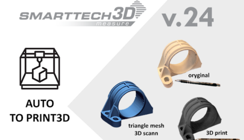
A complete scan with a 3D scanner is typically the first step in reverse engineering items. When a particular part’s geometry necessitates a more exact approach, the arm’s probe is deployed. After being created in PolyWorks, the data is exported to Solid Edge CAD in two different file formats: STL for scanned data (mesh) and IGES (or STP) for probed geometry. Lastly, Solid Edge reconstructs the portion.
Click on the following link Metrologically Speaking to read more such news on metrology.