UNDER SCRUTINIZING EYES
By Pat Brans
PLASMA-FACING COMPONENTS | UNDER SCRUTINIZING EYES
While challenging to build, a system that provides 2D and 3D images of the ITER in-vessel components hours after a plasma shot makes operating fusion devices safer and easier.
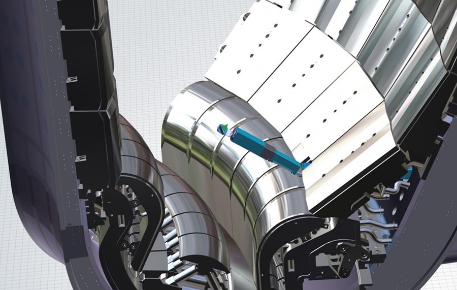
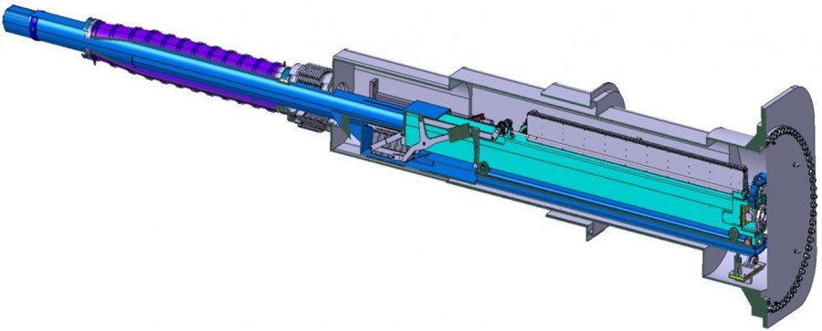
Europe has taken steps towards delivering another first: ITER’s in-vessel viewing system. For the first time, electromechanical arms equipped with laser-scanning systems will reside inside a fusion device. During a pulse, the arms will be folded into cartridges hosted inside vacuum vessel port extensions away from the plasma. Then, when operators want to examine plasma-facing surfaces, they will engage some combination of the six in-vessel viewing systems that will be distributed as evenly as possible in lower ports. Once engaged, the equipment will deploy from its cartridge, and the arm will go straight out on rails until it reaches the interior of the vessel. From there it can tilt up to 75 degrees.
To view the inner surfaces of the plasma chamber, the system will use LIDAR technology, firing a laser beam onto a plasma-facing surface and collecting the reflected light. Each laser shot will result in a single point. By firing millions of beams in carefully planned patterns and combining the resulting points, the system will construct ultra-high-resolution 2D images and 3D clouds-of-points.
“With six of these systems in six different ports, we will be able to visualize more than 95% of the plasma-facing components,” says Aakanksha Saxena, responsible officer of the in-vessel viewing system at the ITER Organization. “The reason some areas won’t be seen is simply because they will not be in line of sight.”
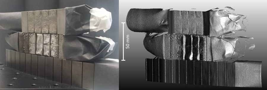
The system will also help solve another important problem—that of measuring erosion. Erosion can be detected by measuring hills and valleys that form when material is deposited on (or removed from) surfaces. To establish a baseline, a scan will be performed before ITER is turned on. Then subsequent scans can be compared to the initial state to make sure erosion does not exceed the limits imposed by the French authorities on nuclear safety.
A unique set of challenges for an opto-electro-mechanical system
The in-vessel viewing system will save time and money by allowing observations during the night shift, when no pulses are run. But building a system that operates just hours after a pulse is no easy task. “The environment is worse than on Mars,” says Gregory Dubus, project manager for the system at Fusion for Energy, the European organization managing Europe’s contribution to ITER. “Our system is required to withstand a unique combination of environmental conditions while keeping up with its expected level of performance. Gamma radiation, neutrons, heat, ultra-high vacuum and a permanent multi-tesla magnetic field make system design and component selection a real challenge.”

The vessel will still be in a vacuum, an environment in which complicated electromechanical systems tend to block. For example, conventional lubricants change state and lose their lubricating properties, resulting in more friction. The friction could then provoke jamming and it could wear on the moving parts. In addition, when exposed to heat and a vacuum, components tend to release gas—a process known as outgassing, which often ruins a vacuum. To overcome such hazards, alternatives must be found.
“Outgassing rates depend on the materials and the processes used to manufacture components,” says Dubus. “If you want a component to operate in an ultra-high vacuum, you cannot use just any kind of cutting fluid or welding technique. To be on the safe side, we require our suppliers to build and test full-scale prototypes to demonstrate that their design and manufacturing processes result in a system compatible with ITER’s vacuum.”
But operating in an ultra-high vacuum is not the only special consideration. “Between plasma shots, the toroidal field magnets are still on, which means the viewing system has to work in very high magnetic fields (7 to 8 tesla), which render standard actuators inoperable,” says Dubus. “On top of that, the environment is highly radioactive, full of neutrons and hot. Temperatures are around 70 °C during inspection and up to 120 °C during baking—high temperatures for electromechanical devices.”
The system is being designed to overcome all possible hazards, because reliability and availability are essential requirements. If one unit shuts down, not only would it render a part of ITER invisible, but any equipment left behind in the chamber would also make it impossible to run another pulse. To minimize this risk, special care is being taken to enhance system reliability and ease maintenance. All components of a single viewing system will be embedded in a single cartridge so that the equipment can be retracted in one operation and transferred to the ITER Hot Cell for repair. And just in case there is still a failure, special procedures and features are being developed to recover equipment from the vacuum vessel with negligible impact on ITER operations.
Validating assumptions
“The plan is to receive components for Assembly Phase II*,” says Saxena. “When they are delivered, they will have to go through acceptance testing, and operators will have to be trained. We will have a dedicated lab on the ITER site to test and commission our components before they get installed in the machine.”
The team is approaching the end of the preliminary design phase, and plans are underway to start work towards the final design review within months. Fusion for Energy has already started developing a full-scale prototype. “We consider it a risk-mitigation strategy to build a prototype now instead of waiting for final design,” says Dubus, “This will allow us to validate our assumptions early enough to make adjustments if necessary.”
*ITER Assembly Phase II will run from June 2026 to June 2028.


