
By: Mahr Marketing Team
Shape is a relatively easy characteristic to determine in many ways: after the measurement, the data is filtered to determine the results. It is one of the most fundamental measurements to support many manufacturing processes – nevertheless, some steps are repeatedly executed incorrectly. This article examines the most common errors and revisits and explains the basics of form measurement.
In the simplest case, the form measurement includes a measuring probe and probe arm with a probe element. This is moved along an ideal circular or linear path in order to acquire data on the probe movements relative to this ideal geometry. The analysis is usually quite straightforward: the measured data points are filtered and mathematical operations are performed on them to determine the results. While it is one of the most basic measurements to support many manufacturing processes, some steps are often performed incorrectly. Errors are particularly common when choosing the filter and the button element.
Incorrect filters used
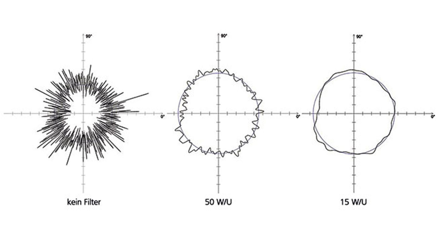
Historically, 50 W / U was used as the default value for roundness measurements. While this filter may be suitable for many uses, it is not suitable for all. The new DIN EN ISO 1101: 2017-09 enables a suitable filter setting to be specified directly in the drawing with any shape tolerance. Nevertheless, it is still true that the correct choice of the filter must be based on the measurement task. It is the responsibility of construction, work planning, and quality management to determine requirement-related filter settings, to record these in-house standards, and to prescribe them for all internal and external suppliers.
Realistically, shape measurement is a process of measuring shape deviations. Traditionally it is carried out in air-conditioned laboratories by highly qualified specialists, but nowadays it is often carried out directly in production by employees who are entrusted with a wide range of tasks. Regardless of whether form or roughness measurement: the procedure is essentially the same. In any surface measurement, many sample points are typically used to represent the entire surface. These points are then filtered to get only the data you want. For example, when testing the surface roughness, the shorter wavelength data is retained for analysis, while the shape-related data is discarded because this information is not needed. In contrast, when measuring the shape, the short wavelength data is filtered out in order to measure the long wavelength data representing the shape. This is the first point where many users make mistakes: The subtle nuances of filtering are not always readily understood and therefore the wrong filters are often chosen.
The shape measurement filters are confusing for many metrologists. When discussing the measurement of surface roughness, for example, the filter settings are referred to in terms of millimeters or inches. When the filter is set to 0.8 mm, it is generally understood that surface deviations of less than 0.8 mm are considered surface roughness, while elements larger than 0.8 mm are considered to be surface defects.
Shape filters for roundness measurements, however, are usually specified as an angle size rather than length or distance. To make things even more confusing, the specifications are not given directly in degrees, but in a unit called ‘waves per revolution’ or W / U (UPR). Many users choose 50 W / U as the typical standard value. This means that the length of the filter is 1 / 50th of a circle – 7.2 degrees.
Consider workpiece diameter for filter selection
However, the arc length, which corresponds to 7.2 degrees on the surface of a round object, changes with the diameter (d) of the object. A simple formula for the circumference of a cylinder is: π * d. So a 4mm diameter cylinder would have a circumference of 12.57mm – and therefore 7.2 degrees would cut out an arc length that measures 0.25mm along the surface. If, on the other hand, a cylinder with a diameter of 20 mm is to be measured, this would have a circumference of 62.83 mm, and the 7.2 degrees would correspond to an arc length of 1.26 mm. If the same 50 W / U filter setting is maintained on the measuring device, then in the case of the larger part, five times greater surface deviations are taken into account as the boundary between the features of shape and surface roughness.
The opposite is also sometimes the case: if there is no understanding that the filter setting has a significant influence on what is filtered out of the data or retained for the analysis, measurement technicians may be tempted to choose a different setting. A different value would change the results, however, and lead to a result that “looks better”, but is not really correct for the size of the test item. The bottom line is that the filter should be set correctly for the particular target.
Incorrect Probe Size
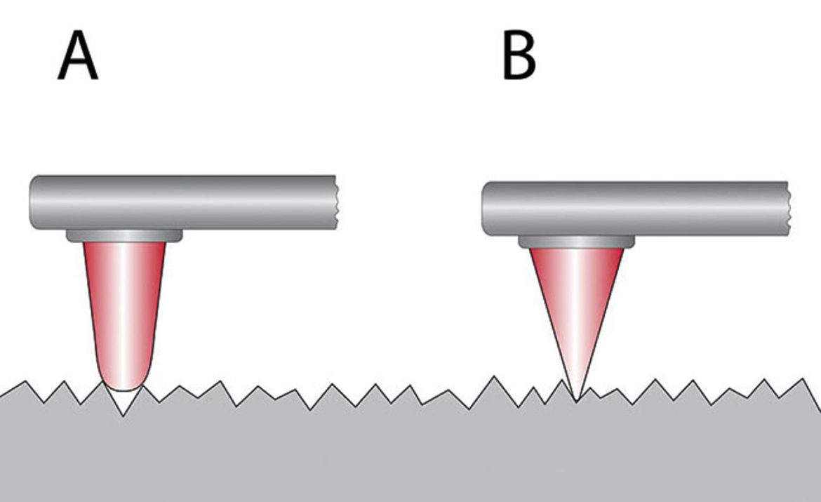
A second common mistake is that users rely on a single probe size to measure all parts, regardless of the size of the device under test. In fact, the stylus ball of the stylus element itself represents a mechanical filter that should be selected according to the workpiece size and the maximum measurable number of shafts per revolution.
The problem can be clearly illustrated using the example of a small component with a diameter of 4 mm: If the measuring surface is scanned with a probe with a probe element that is too large, it cannot run well along the surface and precisely follow the ups and downs of the peaks and valleys. If probe elements are used on a probe that approximate the size of the workpiece diameter itself, it becomes very difficult to obtain a good evaluation of the surface. In this case, the use of this probe element effects mechanical filtering – even before any mathematical filtering takes place. VDI / VDE 2631 Part 3 gives the user a guideline for selecting the correct probe element based on the W / U settings, the maximum expected single shaft depth and the test object diameter.

Conclusion
Although form measurement is one of the basic tasks to support numerous manufacturing processes, many users often incorrectly perform some aspects of it. This can affect both the quality of the measurements and the overall quality of the end product. By following a few basic steps, such as the correct application of the most suitable filters for the respective situation and the determination of the correct data for the respective use case, an exact result can be ensured. The use of the most suitable accessories, such as stylus balls precisely dimensioned for the application, brings the user a good deal forward in the direction of improved measurement data quality – and thus ultimately a higher workpiece quality.
To know more, check Mahr.