
A well known research institute in East Asia develops large-scale aspheric optical
mirrors and lenses for space applications. The mirrors, manufactured with a high
surface quality of λ/30 rms and a diameter up to 2 m, are used in high resolution
satellites or large telescopes. In the testing process of the space optics, a Newport
HXP series Hexapod 6-axis parallel kinematic motion positioner plays an important
role for metrology and quality control.
Due to a high cost of launching pay loads into space, researchers have discovered
ways to reduce size and minimize weight of optical systems used in the satellite. To
produce a smaller overall packaging that is lighter and more cost-effective, a single
large high precision aspheric lens or mirror has replaced multi-lens array that is
more complex in design. As image quality is a key element of the optical system,
surface quality of this monolithic aspheric lens or mirror is fully characterized after
fabrication in order to avoid possible deterioration of overall imaging in satellite
CCD camera.

In the test set-up, a small reflective mirror or a lens, which represents a CCD camera
inside the satellite, is mounted on a motorized platform for measurements of
Modulation Transfer Function (MTF) and Wave front Distortion Error (WDE) of the
device under test (DUT), which is the large aspheric lens or mirror placed in the
beam path. When a collimated beam passes through or gets reflected from the
DUT, the change in shape of a wave front is observed and compared to the incident
wave front, providing an indication of the optical surface quality. As the DUT comes
in various sizes and requires testing under varying incident beam angles, the
controlling optics need five distinct freedoms of motion: two for positioning to the
center of incident beam, two for tip-tilt adjustment and one for focusing along the
optical axis.
As it became evident that alignment is the most labor-intensive and time-consuming
part of testing process, researchers approached Newport for a Hexapod solution as
an alternative to their existing setup using motorized linear and rotary stages in a
Space Optics Testing and Metrology with Newport Hexapod combined stack. With the stacked stages, it took several days to reconfigure the setup for a new DUT, mainly because it was difficult to relocate the pivot point of the optics following any change in height of optical axis or focal distance of the mirror or the lens. Moreover, due to an error contributed from each axis movement in the stack, it was not easy to estimate the travel lengths required in all axes to reach a desired position in 3-D coordinate within a tight tolerance.
Thanks to dual coordinate systems provided by the Hexapod control algorithm and
its ability to define virtual pivot points, overall production cycle times are greatly
reduced, minimizing the cost of operation.
“It took almost one week for an optical system qualification and characterization
process before arrival of the Newport hexapod. Now, it takes no more than two
days for us to complete the test cycle”, a researcher says.
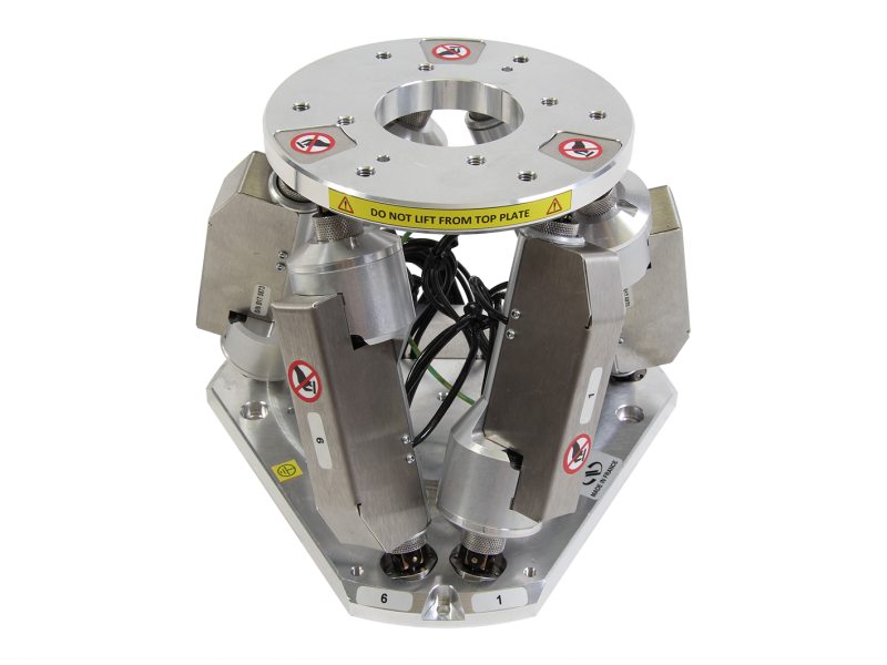
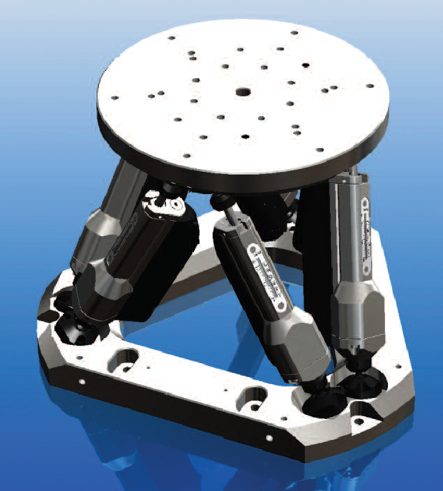
The Newport HXP100 series Hexapod, driven with six high performance DC servo
motor LTA actuators, provides six degrees of freedom that are X, Y, Z, pitch, roll and
yaw. A virtual pivot point allows the user to freely choose the rotation center and it
helps minimize the time to reconfigure the setup, following any shift in the position
of optical components or beam orientation. The HXP100 provides an option to
relocate the entire coordinate system so that a single user-defined coordinate
system can be used to control all the active components including laser beam, DUT
and reference optics. A dedicated Hexapod controller HXP100-ELEC provides a high
speed Ethernet TCP/IP communication interface, advanced motion profiler with
synchronized control and various software program libraries including LabVIEW to
help ensure a smooth programming for integrated software control in user
environments.
APPLICATION NOTE :-
Travel range (X) ±29 mm
Travel range (Y) ±26 mm
Travel range (Z) 28 mm
Travel range (Θx) ±12°
Travel range (Θy) ±10°
Travel range (Θz) ±20°
Min. incremental motion (X, Y, Z) 0.5 μm
Min. incremental motion (Θx, Θy, Θz) 5 μrad
Repeatability (X, Y, Z) 0.5 μm
Repeatability (Θx, Θy, Θz) 17 μrad
Max. speed (X, Y, Z) 1 mm/s
Centered load capacity 200 N
Rigidity (Z) 40 N/μm
For additional information, please contact Newport applications and sales engineers at tech@newport.com.