Users can quickly and easily build and save surface profile point grid objects to the Automate Plan using the Surface Grid tool in Verisurf Automate. Once modified and defined, these Surface Grid objects enable the inspection of surfaces and the generation of real-time profile deviations from the engineering model as intended.
The surface Grid produces uniformly spaced points that advance along the chosen surfaces at user-specified intervals. Additionally, it creates the probe path as a component of the same useful tool. A UV or XY-spaced pattern can be used to control spacing.
Using Surface Grid
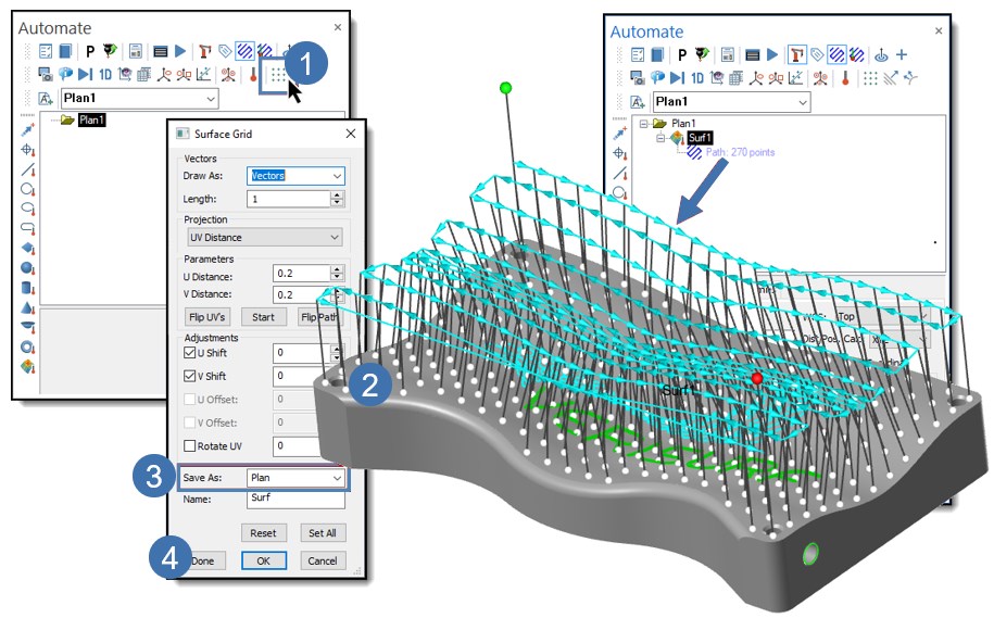
The following process is used in Automate to set up and define a Surface Grid measurement process.
- From the Automate toolbar, select Surface Grid 3D Metrology Software, Training and CMMs to add the Surface Grid object to the Plan (shown below).
- The Surface Grid dialog opens and prompts you to Select Surface. The active dialog settings control the Surface Point creation.
- In the Save As a control, verify that the Plan is selected.
- Select Done for each Surface Grid object required; the dialog box remains open for multiple selections. Choose OK to close the function.
Features may also be constructed from Surface Points Objects if required:
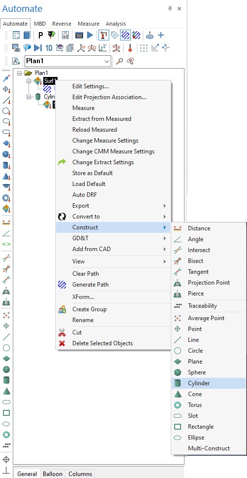
Credits: Verisurf
Click on the following link Metrologically Speaking to read more such blogs about the Metrology Industry.
